


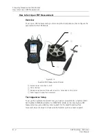


Frequency Response Function Module
How to Set Up an FRF Measure
ment
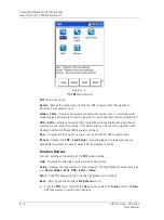
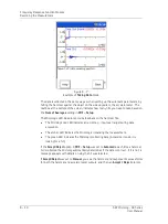
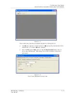
Figure 8 - 3.
The FRF
New
Measurement Setup Screen (Expanded View).
Function Buttons
Function buttons at the bottom of the screen include:
Help
– Access the Microlog’s context sensitive help.
Save
–
Saves the current settings. Enter a filename to identify the measurement
settings.
Start
– Take FRF data using the current settings.
Back
– Returns you to the FRF menu.
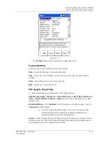
FRF Analysis Setup Fields
•
Enter appropriate setup information in the following fields:
Response Channel(s)
–
CH1 (Force = CH4), CH2 (Force = CH1), CH1 & CH2 (Force =
CH4),
or
CH1 & CH2 & CH3 (Force = CH4),
Specify the input channel(s) for the FRF
measurement.
Excitation Method
- Set to
Hammer
for FRF acquisition and modal analysis, or set to
Continuous
for ODS analysis.
If you are performing ODS analysis, refer to the instructions that
accompanied your ODS software for additional information on
Microlog settings required by that application.
Sensor –
Select the appropriate preconfigured sensor from the setup screen’s context
sensitive sensor list. Note that the specified sensor type determines available options
and engineering units for subsequent setup fields.
SKF Microlog - GX Series
8 - 5
User Manual


