


Conformance Check Module
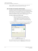
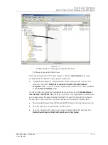
How to Set Up or Customize Conformance Test Templates
Tab Overview
Measurement
– Specifies the vibration measurement sensor type and sensor location
settings.
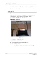
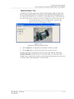
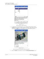
Machine Picture
– Displays a user specified picture or diagram of the test machine
showing sensor placement locations.
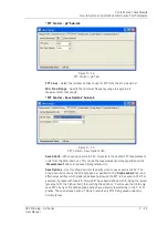
FFT Control
– Allows FFT parameters to be changed.
Grade Labels
– Specifies the number of test grades (alarms) and the label for each.
Grade Bands
– Specifies the number of test measurements (bands) for each sensor
location, defines the specified measurement types and measurement frequency range.
Grade Boundaries
– Specifies grade level settings (alarm levels) for each test grade at
each measurement location.
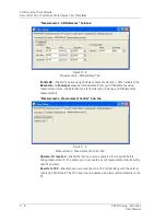
“Measurement” Tab
Measurement
tab settings specify the type of vibration sensor used, the number of test
measurement locations, and the sensor placement orientation(s) for each measurement
location. Note that the type of sensor specified (accel, vel, disp, etc.) determines the
type of FFT spectrum collected (acceleration, velocity, displacement, etc.).
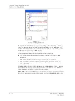
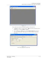
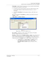
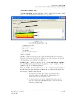
“Measurement - Transducer” Sub-tab
Figure 9 - 6.
Measurement – Transducer Configuration Tab.
Measurement Units
– Select the desired measurement units from the drop-down list.
Note that any derived (integrated) measurement units may be used to specify individual
measurement bands.
Sensitivity
– Use the alphanumeric keypad to enter transducer sensitivity in millivolts
(mv) per Engineering Unit (EU).
ICP
TM
– Specify if ICP powering should be applied to transducer (
On
) or not (
Off
”). Note
that when selecting the measurement units from the drop-down list, the normal
transducer ICP powering is deduced and applied. This default behavior should be
overridden, if required.
9 - 6
SKF Microlog - GX Series
User Manual


