


Frequency Response Function Module
How to Set Up an FRF Measurement
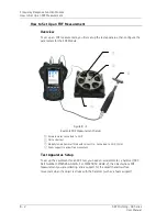
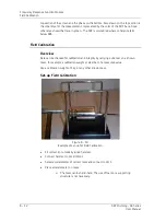
To set up the FRF test apparatus:
•
Fit the correct tip to a modally tuned hammer. (The hammer is used to create the
force that is to be measured in the FRF.)
Use a harder tip for high frequency and a softer tip for lower
frequency measurements.
•
Connect the modally tuned hammer to the Channel
R (CH 4)
input of the Microlog.
•
Support the part under test to allow free movement (e.g., on foam support as
illustrated).
•
Select an accelerometer of the correct mass and connect it to Channel 1 of the
Microlog. (The accelerometer is used to measure the response to the hammer input
of the FRF.)
The accelerometer mass should be low in relation to the test
piece, that is less than 10%.
•
Connect the accelerometer to one of the sides of the object you are going to
measure.
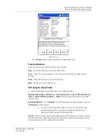
FRF Module Setup
Some settings are pre-set to simplify user setup. Pre-set measurement parameters
are:
•
Pre-trigger delay – set to 10% of block length
•
Trigger level – set to 10% of input range
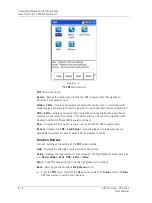
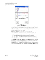
All other settings are configured within the FRF Module.
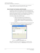
•
From the
Home
screen, use the arrow keys to highlight the
FRF
icon, and press an
Enter button. The FRF menu displays.
SKF Microlog - GX Series
8 - 3
User Manual


