Rostock MAX v2 Assembly Guide – 4thEd.
8.2 – Installing the Upper Tower Mounts
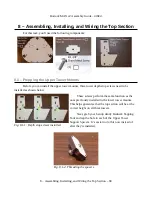
When installing the Upper Tower Mounts, make sure that you've got the top plate base oriented
so that the laser engraved axis labels are face-up.
The The upper tower mounts don't fit in the tower sockets without being a bit clever in the
installation process. We'll start with the X axis tower support.
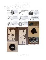
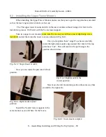
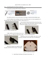
Take two upper tower mounts (make sure the one on your left has a tower depth stop screw
installed!) and set them into the tower socket as shown in Fig. 8.2-1.
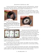
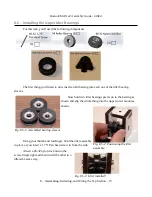
Once you've gotten them “staged” as shown, carefully
rotate the right-side mount's edge nearest the center of the top
plate base “out”. This will result in the part being in the
position shown below.
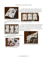
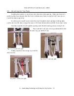
Now you can rotate the part into it's final
position.
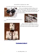
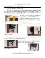
Now move the left mount into position the same way that
you did for the right side.
Install the Y and Z tower supports in the
same manner as you did here for the X axis.
8 – Assembling, Installing, and Wiring the Top Section – 69
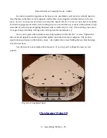
Fig. 8.2-1: Staged tower mounts.
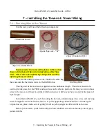
Fig. 8.2-2: Right mount in the
correct position.
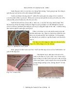
Fig. 8.2-3: Right mount in final
position.
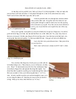
Fig. 8.2-4: X axis mount complete.

