Rostock MAX v2 Assembly Guide – 4thEd.
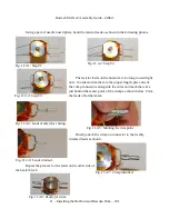
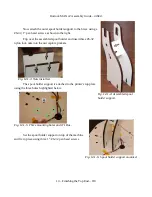
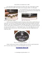
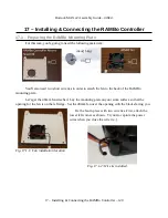
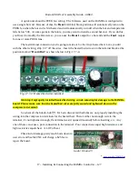
Now rotate the bed support such that the two notches in the “front” of the support is pointed
towards the front of the machine. The notches allow the Onyx power LED to clear the support.
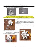
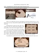
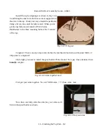
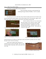
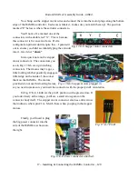
Get a #4 flat head screw and a spacer from the Onyx parts
pack. Insert the screw through the Onyx, the bed support and
finally the plastic spacer.
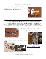
Turn the screw just enough that it grips the first threads in the t-nut that you installed when you
built the base. The idea here is to keep the whole assembly from moving around while you finish the
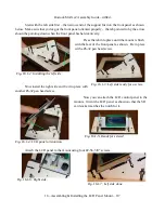
installation. Now you can install the remaining 5 remaining screws & spacers. What I do is work in a
counter-clockwise direction around the Onyx. I set a screw and then slide a spacer under it with the tip
of a small screwdriver until the screw falls through the spacer. You can then tighten the screw a little
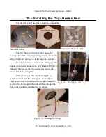
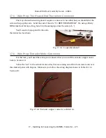
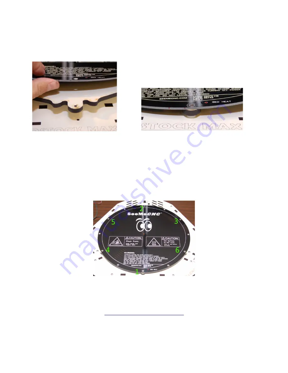
bit before moving on to the next screw. After you've got all the screws started, tighten them in the
order shown below.
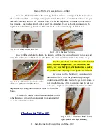
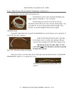
Finally, carefully remove the little tab of Kapton tape you covered the center thermistor hole
with. You want to remove it slowly so you don't pull the RTV out of the hole.
Checkpoint Video #20
15 – Installing the Onyx Heated Bed – 115
Fig. 15.1-3: Bed support aligned.
Fig. 15.1-4: First screw.
Fig 15.1-5: Screw tightening pattern.

