Rostock MAX v2 Assembly Guide – 4thEd.
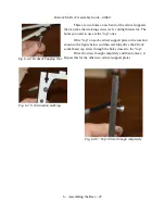
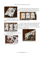
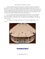
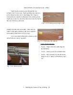
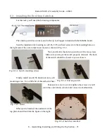
Now slide an idler bearing on to the spacers, followed by two more spacers.
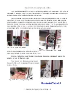
Now you can complete the assembly by fitting a tower
support to the two screws. Install a #6-32 nylon lock nut to
each screw – don't tighten it too much. Finger tight is fine. You
want a bit of “wobble” in the assembly to assist in getting the
top of the base installed.
Repeat this assembly process for the other two
motors.
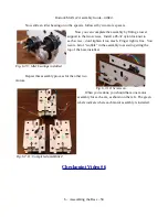
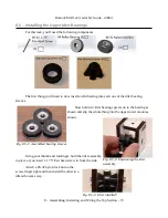
When you're done, you should have one motor
assembly for each axis, as shown on the left. The green
labels indicate where each motor assembly is installed.
Checkpoint Video #6
6 – Assembling the Base – 58
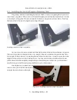
Fig. 6.7-9: Idler bearings installed.
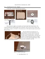
Fig. 6.7-10: Screws on.
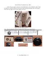
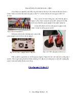
Fig. 6.7-11: Completed assemblies!

