Rostock MAX v2 Assembly Guide – 4thEd.
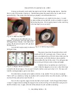
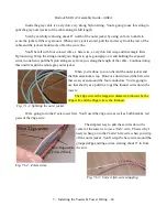
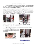
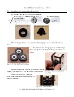
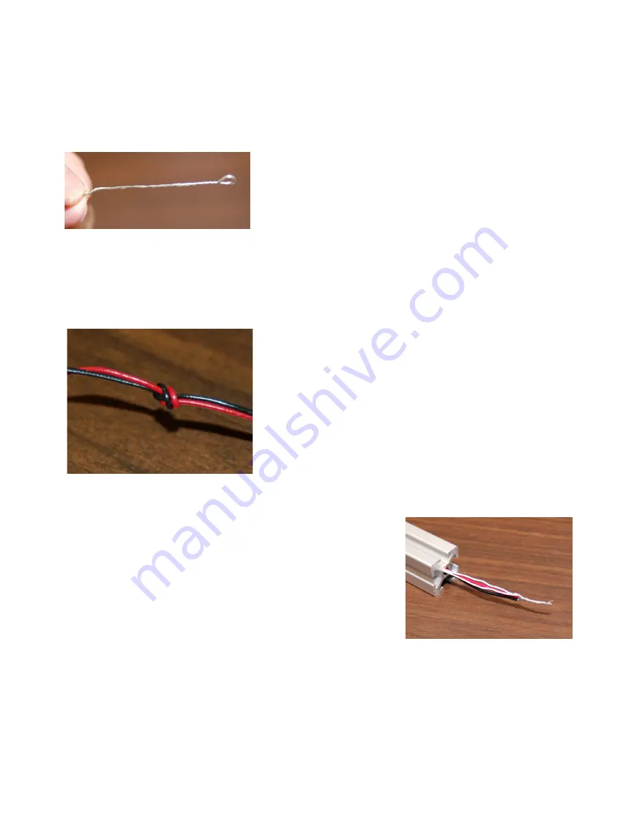
At the other end of your fish-wire, fold over about 2” worth and spindle it. This will make the
wire end more stiff and will allow it to be pushed through the center of the extrusion more easily.
You'll want to flatten that little loop at the end as well.
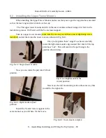
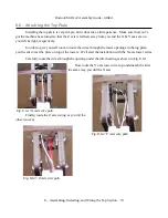
Carefully push the fish-wire through the extrusion until it
comes out the other end. Grasp the end of the fish-wire and
slowly pull it through. Guide the main wires into the opening
in the extrusion as you pull. Once the wire has moved about an
inch in, you can use the fish-wire to pull it the rest of the way
through.
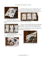
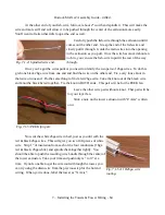
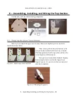
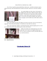
Once you've got the wires pulled, you need to identify the two pairs of 26ga wires. To do this
grab one black 26ga wire from one end and find that wire on the other end. Tie a very loose knot in
that wire on one end. Do the same thing to find a red 26ga wire. Take the knot out of the black wire
and knot the black & red together. Tie the knot in BOTH ends. This pair will be for the PEEK fan.
Leave the other wire pair without a knot. That pair will be
for your layer fan.
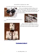
Stick a note on the tower extrusion with “Z Axis” written
on it.
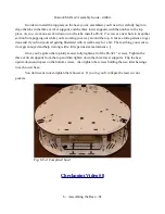
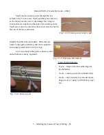
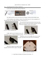
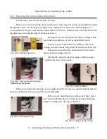
Now cut the white 26ga wire in half, just as you did with the
red & black 26ga wires. This will give you two 10ft pieces of white
wire. Strip 1” of insulation from each of the four conductors (18ga
red & black, 26ga white) and spindle them together tightly. You
should be able to push the resulting wire bundle through the center of
the tower extrusion. Take your time and push only ¼” to ½” at a
time. If you're unable to get the wire routed through the tower, you
can try using the drain wire from the previous step for the hot end
wiring. When you're done, label the tower as “X Axis”.
7 – Installing the Towers & Tower Wiring – 64
Fig. 7.1-4: Spindled wire end.
Fig. 7.1-5: PEEK fan pair.
Fig. 7.1-5A: 18/26ga wire
routing.


