Rostock MAX v2 Assembly Guide – 4thEd.
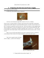
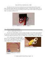
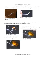
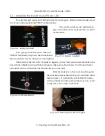
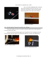
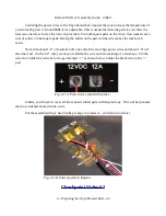
Once you've done those, I want you to attach one 22-16awg ring terminal and one 22-16 female
spade terminal to each of the 8”, 18ga wires. (Black, White, and Green).
Finally, attach two 22-16awg female spade terminals to each end of the last 3”, 18ga black wire.
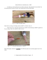
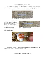
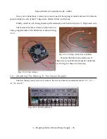
The last task for this section is to attach two 22-
16awg ring terminals to the 60mm fan as shown in Fig.
3.3-3.
Set aside the 60mm fan and the one 3”,
18ga wire you put the female spade connectors
on. We'll get to those in a later step.
3.4 – Attaching The Wiring To The Power Supply
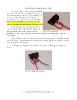
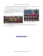
The first thing I want you to do is remove the screws from the terminals marked “V+”, “V-”,
“
⏚”
, N, and “L”.
3 – Preparing the Hot End and Power Supply – 36
Fig. 3.3-3: Crimp connectors installed.
Fig. 3.3-4: Fan crimps.
Fig. 3.4-1: Screws removed.

