Rostock MAX v2 Assembly Guide – 4thEd.
9.7 – Installing the Axle Adapters
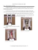
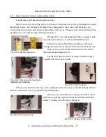
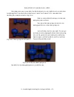
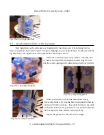
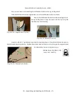
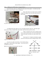
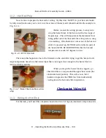
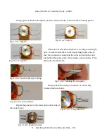
Set one Ball Joint Arm on the two mounting posts on the front face of the IM Carriage as shown
below.
Next, install two #4 x 1/2” sheet metal screws
along with two #4 flat washers to hold the Ball Joint Arm
in place.
9.8 – Adjusting the Belt Tension
The mounting for the top idler pulleys is designed to allow you to increase the tension on the
belts if necessary. Setting proper belt tension is more magic than science at this point, but the
following instructions will get you at a pretty good default tension.
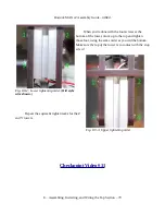
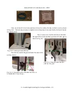
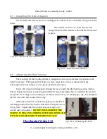
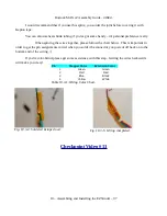
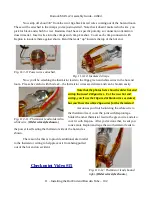
Insert a P2 screwdriver diagonally through the tower, under the idler bearing as shown below.
This technique depends on you having pulled the belt reasonably tight when you installed the last belt
clamp into the carriage you're working on. If that wasn't the case, you should pop a clip out and tighten
the belt a bit more and re-install the clamp.
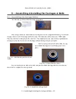
When the screwdriver is under the pulley, you should see
a small gap under the screw head as indicated by the green arrow
in Fig. 9.8-1. Tighten the #6-32 nylon lock nut usng a 5/16”
wrench and a screwdriver.
DO NOT OVER-TIGHTEN THE
SCREW! IT WILL PULL THROUGH THE MELAMINE AND
WILL NO LONGER HOLD THE IDLER IN PLACE!
Checkpoint Video #12
9 – Assembling & Installing the Carriages & Belts – 88
Fig. 9.7-1: Ball Joint Arm installation.
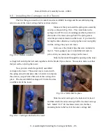
Fig. 9.7-2: Ball Joint Arm installed.
Fig. 9.8-1: Tensioning the belts.

