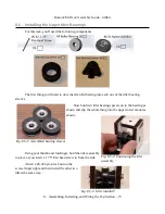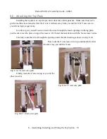
Rostock MAX v2 Assembly Guide – 4thEd.
6.8 – Installing the Tower Supports
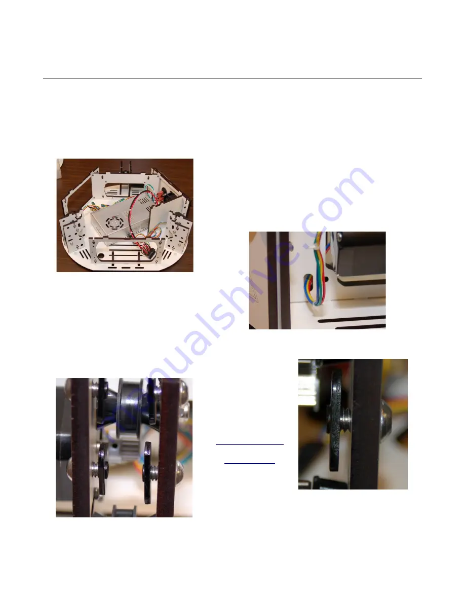
Now let's get the three tower support & motor assemblies attached to the base of the machine.
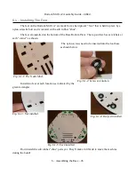
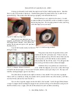
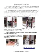
Drop the X and Y axes in as shown below. Install two #6-32, 1” pan head screws into each one,
just a bit more than finger tight. We want a bit of wobble to help with the installation of the top. Note
that the axis of each tower support location is laser engraved into the material. They're labeled “X”,
“Y”, and “Z” respectively.
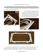
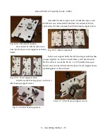
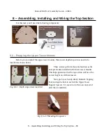
The Z axis tower & motor support installs the
same way as the other two. The wires for the Z axis
stepper motor should be routed through the lower hole in
the power supply bracket as shown below. The connector
is a tight squeeze, but it WILL fit.
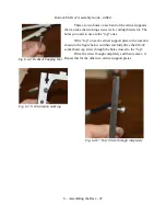
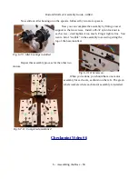
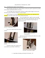
Now you need to install four of the ¼-20 cap
head screws and four T-Slot nut plates into each tower
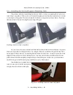
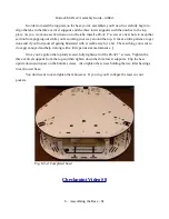
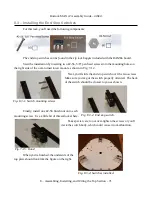
support assembly. Only thread the T-Slot nut plates
enough to feel the end of the screw catch all the threads
in the plate – the space is needed in order to properly fit inside the
slot in the tower.
Checkpoint
Video #7
6 – Assembling the Base – 59
Fig. 6.8-1: X & Y Tower supports installed.
Fig. 6.8-2: Z Axis motor wire route.
Fig. 6.8-3: T-Slot nut plates installed.
Fig. 6.8-4: Depth example.

