Rostock MAX v2 Assembly Guide – 4thEd.
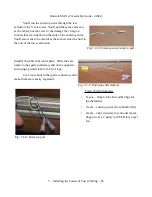
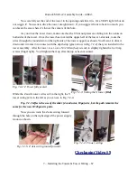
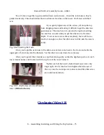
You'll run the end-stop wires through the last
extrusion, the Y axis tower. You'll pull these the same way
as the others, but take care to not damage the crimp on
sockets that are installed on the ends of the end-stop wires.
You'll also want to be careful as the sockets enter the hole in
the end of the tower extrusion.
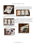
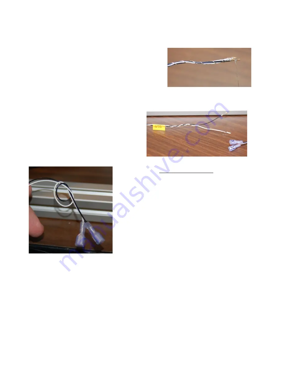
Identify three black & white pairs. Write the axis
name on the spade connectors and on the opposite
end using a printed label or a bit of tape.
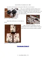
Tie a loose knot in the spade connector end to
make them more easily separated.
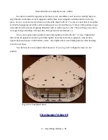
Tower Wiring Summary
•
X-axis – 18ga for the hot end & 26ga for
the thermistor.
•
Y-axis – end stop wires (from Rambo Kit)
•
Z-axis – 22ga (4 wires) for extruder motor;
26ga (4 wires, 2 pairs) for PEEK fan, Layer
fan.
7 – Installing the Towers & Tower Wiring – 65
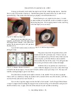
Fig. 7.1-6: End-stop wires ready to pull.
Fig. 7.1-7: End-stop ends marked.
Fig: 7.1-8: End-stop pair.

