


Rostock MAX v2 Assembly Guide – 4thEd.
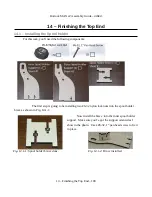
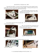
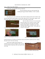
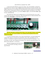
Get your soldering iron heating and insert the ends of the fan wires into the two solder pads on
the bottom right hand corner of the RAMBo controller as shown.
Make sure that you install the wires as shown –
the red wire needs to be in the pad marked with the “+”
next to it. If you install it the other way, the fan may run
in reverse and won't cool the MOSFET chips on the
RAMBo very well. (The MOSFET chips are those little
black squares in the photo in Fig. 17.2-2.)
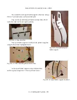
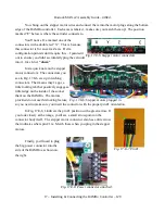
Hold or tape the wires into place and flip the RAMBo controller upside down so you can reach
the solder pads on the back side of the board. Solder the leads in place.
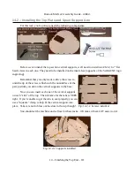
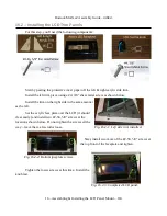
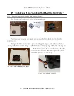
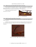
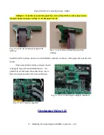
Mounting the RAMBo is very straightforward. Simply set
the RAMBo on top of the mount and slide a plastic roller
between the RAMBo and the mounting plate as shown in Fig.
17.2-4. Insert a #4-40, 3/4” flat head screw in the hole and
tighten a few turns.
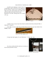
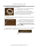
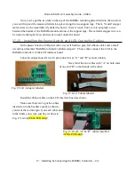
When you've got all four screws started, go
ahead and tighten them all down. Take care to not
over tighten them or you'll damage the circuit
board!
17 – Installing & Connecting the RAMBo Controller – 122
Fig. 17.2-2: Fan wire installation location.
Fig. 17.2-4: Same idea, different screw.
Fig. 17.2-3: Fan wires soldered in.
Fig. 17.2-5: Completed
installation.


