Rostock MAX v2 Assembly Guide – 4thEd.
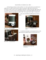
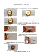
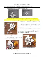
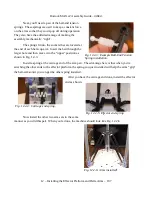
Now strip off about 3/8” from the two 18ga black & red wires coming out of the hot end loom.
These will be attached to the crimps you've just installed. Note that it doesn't matter which side you
pick for black and which for red. Resistors don't have a specific polarity, so connection orientation
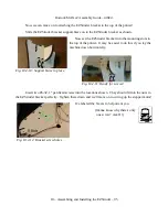
doesn't matter. Insert wires into the crimps and crimp 'em shut. Cover each crimp connector with
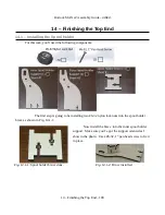
Kapton to insulate them against shorts. Bend the leads “up” towards the top of the hot end.
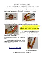
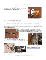
Now you'll be attaching the thermistor leads to the 18ga green and white wires in the hot end
loom. Please be careful with this task – the thermistor wires are delicate and can be broken easily.
Note that the photos here show the older hot end
wiring that used 4 18ga wires. For the new hot end
wiring, you'll use the 18ga red & black wires as stated,
but you'll use the white 26ga wires for the thermistor!
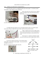
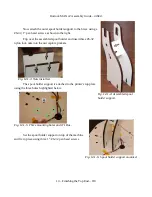
As
soon as you finish soldering the white wire to
the thermistor lead, cover the joint with Kapton tape.
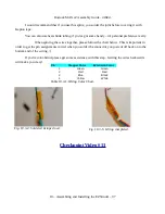
Solder the other thermistor lead to the green wire and also
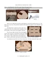
cover it with Kapton. After you've done that, I want you
to use more Kapton and tape the two thermistor leads to
the power lead feeding the thermistor side of the hot end as
shown.
The reason for this is to provide additional strain relief
to the thermistor wiring to help prevent it from being pulled
out of the hot end on accident.
Checkpoint Video #15
11 – Installing the Hot End and Bowden Tube – 102
Fig. 11.3-10: Insulated crimps.
Fig. 11.3-11: Thermistor lead soldered to
white wire. (
Older wire style shown.
)
Fig. 11.3-12: Thermistor leads bound
tight. (
Older wire style shown.
)
Fig. 11.3-9: Power wires attached.

