Rostock MAX v2 Assembly Guide – 4thEd.
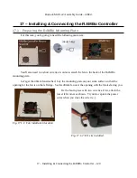
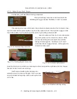
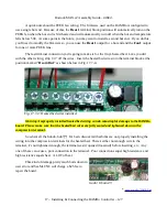
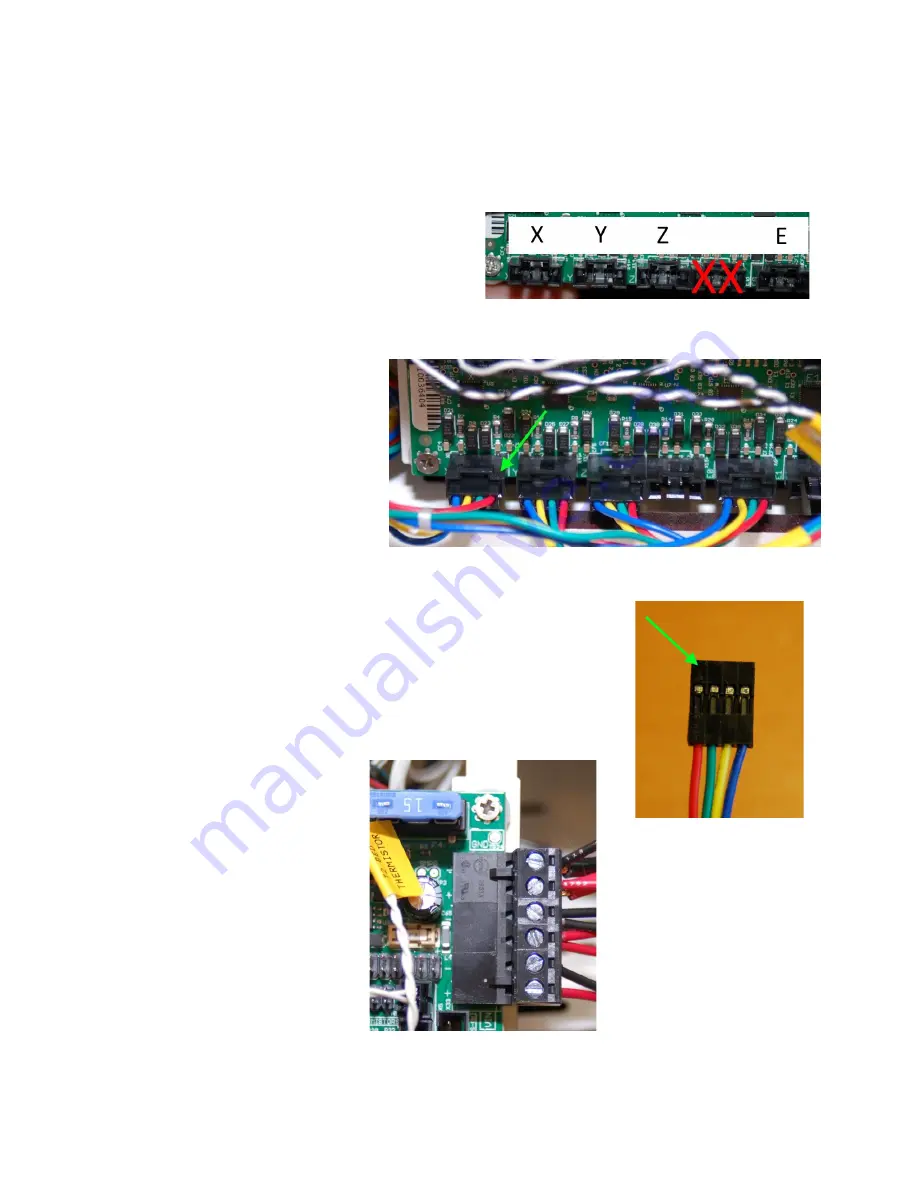
Now bring out the stepper motor wires and connect them into the motor plugs along the bottom
edge of the RAMBo controller. Each axis is labeled – make sure you match them up! The position
marked “E” below is where the extruder connects to.
You'll notice I've marked one of the
connectors with a double red “X”. This is because
this connector is for an extra Z axis. Delta
configuration printers don't require this – I pointed it
out to ensure you didn't accidentally plug the extruder
into it...like I did. *
ahem
*
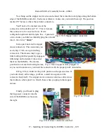
Just a quick note on the stepper
motor connectors. The connectors you
see in Fig. 17.8-6 are 4 pin latching
connectors. That means they've got a
little locking tab that positively engages a
little ledge on the inside of the socket
that's on the RAMBo. The motors
provided do not use this locking feature,
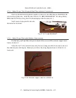
so you need to make sure you insert the connector with the proper pin #1 orientation.
In Fig. 17.8-6, I indicate the pin #1 position with a green arrow. If
you look closely at the image, you'll see a small arrow point on the
connector body itself. The stepper motor connector also has a little arrow
that indicates where pin #1 is. Match these when you plug in the stepper
motors.
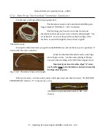
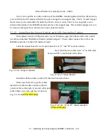
Finally, you'll need to plug
the big power connector into the
side of the RAMBo as shown on
the right.
17 – Installing & Connecting the RAMBo Controller – 129
Fig. 17.8-5: Stepper motor connectors.
Fig. 17.8-6: Stepper motors plugged in.
Fig. 17.8-8: Power connector attached.
Fig. 17.8.-7 Pin #1.

