Installation
Page 4-20
In addition to the physical wiring connections, the analog
output parameters must be set up for the specific application.
The
2010D
allows the scaling and averaging of each analog output
to be independently set from the Photometer Parameters screen,
as described beginning on Page 9-12.
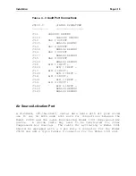
Instrument Solenoid Connections
If the Instrument Solenoid option is installed, external
solenoid valves may be attached to connector J10 and
automatically activated when an associated calibration Sequence
or Point is active. J10 is located on the option module's rear
panel (see Figure 4-1), which may also support other connectors
related to the Photometer or Permeation Oven, depending upon
what options are installed.
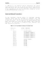
Table 4-12 Instrument Solenoid Connections
2010D
J10
SIGNAL SIGNATURE
_______
_________________
J10-1
CHASSIS GROUND
J10-2
INSTRUMENT SOLENOID 1
J10-3
INSTRUMENT SOLENOID 2
J10-4
INSTRUMENT SOLENOID 3
J10-5
INSTRUMENT SOLENOID 4
J10-6
INSTRUMENT SOLENOID 5
J10-7
INSTRUMENT SOLENOID 6
J10-8
J10-9
CHASSIS GROUND
J10-10
GROUND
J10-11
GROUND
J10-12
GROUND
J10-13
GROUND
J10-14
GROUND
J10-15
GROUND
Summary of Contents for 2010D
Page 1: ...MODEL 2010D GAS DILUTION CALIBRATOR OPERATIONS MANUAL I N S T R U M E N T S...
Page 3: ......
Page 20: ...System Operations Page 3 2 Figure 3 1 The Model 2010D Front Panel...
Page 42: ...Installation Page 4 15 Figure 4 1 Rear Panel...
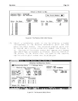
Page 63: ...Operation Page 5 7 Figure 5 5 The Dilution Status Screen Figure 5 6 The Ozone Status Screen...
Page 177: ...MODEL 2010D GAS DILUTION CALIBRATOR SCHEMATICS...
Page 178: ......


