Serial Communications
Page 7-26
_________________________________________________________________
Where:
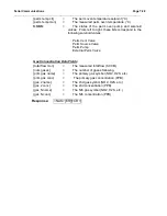
{dilution status} =
{dil mfc ctl}, {dil mfc mon}, {o3 mfc ctl},
{o3 mfc mon}, {src mfc #}, {src mfc ctl},
{src mfc mon},{sys temp},
DDDDDDDDDD, SSSSSS
{ozone status} =
{o3 temp ctl}, {o3 temp mon}, {o3 lamp ctl},
{o3 lamp curr}, {o3 lamp int}, {o3 conc ctl},
{o3 conc mon}
{perm status}
=
{perm mfc ctl}, {perm mfc mon},
{perm temp ctl}, {perm temp mon}, MMMM
{photo status}
=
{photo avg}, {lamp temp ctl},
{lamp temp mon}, {lamp curr ctl},
{lamp curr mon}, {lamp intensity},
{det samp}, {det ref},
{gas temp}, {gas pres}, {gas flow}, PPP
{gas status}
=
{total flow mon}, {num gases},
{prim gas name}, {prim gas conc},
{gas 2 name}, {gas 2 conc},
,
{gas N name}, {gas N conc}
And Where
:
Dilution Data Fields
{dil mfc ctl}
=
The diluent MFC setpoint (SCCM)
{dil mfc mon}
=
The measured diluent MFC flow (SCCM)
{o3 mfc ctl}
=
The ozone MFC setpoint (SCCM)
{o3 mfc mon}
=
The measured ozone MFC flow (SCCM)
{src mfc #}
=
The source MFC number (1 or 2)
{src mfc ctl}
=
The source MFC setpoint (SCCM)
{src mfc mon}
=
The measured source MFC flow (SCCM)
{sys temp}
=
The system temperature
DDDDDDDDDD
=
The states of the dilution unit solenoid valves.
Each character is a 0 or 1, where 1 indicates that the
valve is on. From left to right, these bits correspond to
the following solenoid valves:
Diluent 1 Valve
Diluent 2 Valve
Summary of Contents for 2010D
Page 1: ...MODEL 2010D GAS DILUTION CALIBRATOR OPERATIONS MANUAL I N S T R U M E N T S...
Page 3: ......
Page 20: ...System Operations Page 3 2 Figure 3 1 The Model 2010D Front Panel...
Page 42: ...Installation Page 4 15 Figure 4 1 Rear Panel...
Page 63: ...Operation Page 5 7 Figure 5 5 The Dilution Status Screen Figure 5 6 The Ozone Status Screen...
Page 177: ...MODEL 2010D GAS DILUTION CALIBRATOR SCHEMATICS...
Page 178: ......


