Internal Calibrations
Page 8-11
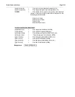
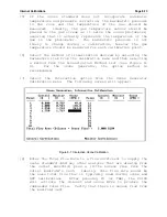
[6] Select the method of linearization desired by selecting the
Parameters item from the calibration menu and then selecting
a method from the Linearization Method list (see Figure 8-
6).
For mass flow controllers,
the Lookup Table
is the
recommended
linearization
method.
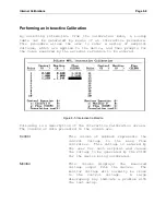
[7] Select the Interactive option from the calibration menu.
The screen shown in Figure 8-5 should appear.
[8] Enter the first control voltage in the left-most column.
The
2010D
will apply this voltage to the control input of
the mass flow controller, causing a flow corresponding to
that voltage to be produced.
[9] Observe that the monitor voltage approaches the control
voltage, indicating that the MFC is sensing a flow. Once
the monitor voltage has stabilized, wait another 60 seconds
before taking a measurement.
[10] Take a measurement from the external flow standard. If the
flow standard requires temperature and pressure correction,
take a temperature reading and apply it and the room’s
barometric pressure to the measured flow in order to obtain
a mass flow value. Enter this value into the column labeled
"Flow" and press the Enter key. The cursor will advance to
the next control voltage field.
[11] Repeat steps 8 through 10 until all calibration points have
been entered.
[12] Press the ESC key. A dialog box will appear, asking if you
want to calculate the coefficients. Answering "yes" will
cause the calibration coefficients to be calculated and, if
the linearization method is linear or polynomial, presented
for review. One particular item to note at this point is the
correlation. For mass flow controllers, the correlation
should be very close to 1.0000 (e.g. 0.99999X), indicating a
close correlation to a straight line. If everything looks
good, answer "yes" again and the calibration will be saved.
Summary of Contents for 2010D
Page 1: ...MODEL 2010D GAS DILUTION CALIBRATOR OPERATIONS MANUAL I N S T R U M E N T S...
Page 3: ......
Page 20: ...System Operations Page 3 2 Figure 3 1 The Model 2010D Front Panel...
Page 42: ...Installation Page 4 15 Figure 4 1 Rear Panel...
Page 63: ...Operation Page 5 7 Figure 5 5 The Dilution Status Screen Figure 5 6 The Ozone Status Screen...
Page 177: ...MODEL 2010D GAS DILUTION CALIBRATOR SCHEMATICS...
Page 178: ......

