Model
2010D
Calibration Setup
Page 6-4
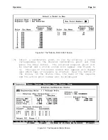
[5] Select a gas for the first component by positioning the
cursor over a Component Gas field and pressing Enter.
Select a gas name and symbol from the drop-down list and
press Enter to proceed to the concentration field. If a
gas is not present in the list, it may be added by
following the procedure on page 6-2.
[6] Enter the concentration of the gas in the cylinder. Be sure
to observe the units of measure listed to the right. If
you want to enter the gas in different units, move to the
next field by pressing F3, change the units as described in
step 7 and move back to the concentration field by pressing
F2.
[7] By pressing Enter over the units for a gas, alternate units
of measure for that gas component can be selected from a
drop-down list. The concentration previously entered in
the field will automatically be adjusted to the selected
units.
[8] Repeat steps 5 and 6 until all components in the Gas
Standard have been entered.
[9] To save the Gas Standard, press the End Sequence button and
answer yes to the confirming dialog box.
[10] To create another Gas Standard, repeat steps 4 through 9.
[11] To return to the main menu, press the End Sequence button
until only the main menu appears on the screen.
Diluent and Source Port Assignments
A diluent gas must be assigned to one or more diluent ports and
a Gas Standard must be assigned to one or more source ports
before dilution calibration sequences can be set up. To assign
diluent gases and Gas Standards to inlet ports, use the
following steps:
[1] Select Gases from the main menu and press the Enter button.
A pop-up menu will appear.
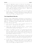
[2] Select Port Assignments and press the Enter button.
Another pop-up menu will appear. This menu lists the
following options: View to view Port Assignments and Edit
to modify the Port Assignments.
Summary of Contents for 2010D
Page 1: ...MODEL 2010D GAS DILUTION CALIBRATOR OPERATIONS MANUAL I N S T R U M E N T S...
Page 3: ......
Page 20: ...System Operations Page 3 2 Figure 3 1 The Model 2010D Front Panel...
Page 42: ...Installation Page 4 15 Figure 4 1 Rear Panel...
Page 63: ...Operation Page 5 7 Figure 5 5 The Dilution Status Screen Figure 5 6 The Ozone Status Screen...
Page 177: ...MODEL 2010D GAS DILUTION CALIBRATOR SCHEMATICS...
Page 178: ......


