Installation
Page 4-15
Status Input/Output Port
The Model
2010D
Calibrators are equipped with 24 digital
Input/Output bits which may be programmed to control calibration
sequences and provide status output information on the
calibration process.
Relay contact closures or TTL logic connected to the appropriate
bit(s) and corresponding common(s), are used to activate
programmed calibration sequences. The active state is with the
contact closed or a logic level of 0 for TTL logic.
The TTL
device must be capable of sinking 1 ma of current (5 mw of
power) per bit. All unused leads should be covered with
insulation.
Status output ports can be used to interface with Opto-22
devices. The signal levels are TTL voltages. The current into
the pulled-up open collector transistor outputs should not
exceed 20 ma. The bits are low in their active state. For
example if Instrument 1 bit were activated, the collector would
be pulled low.
---
CAUTION
---
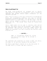
Under no circumstances should the current
into each control output bit be allowed to
exceed 20 ma.
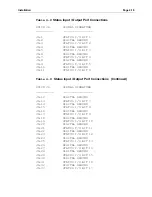
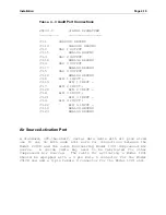
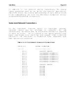
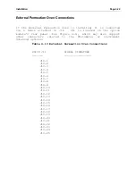
The signatures and connections are shown in Table 4-8, below.
See Figure 4-1 for pictorial drawing of the rear panel.
The Status Input/Output connector J6 on the rear panel of
the Model
2010D
is a female type DB-50 connector.
Summary of Contents for 2010D
Page 1: ...MODEL 2010D GAS DILUTION CALIBRATOR OPERATIONS MANUAL I N S T R U M E N T S...
Page 3: ......
Page 20: ...System Operations Page 3 2 Figure 3 1 The Model 2010D Front Panel...
Page 42: ...Installation Page 4 15 Figure 4 1 Rear Panel...
Page 63: ...Operation Page 5 7 Figure 5 5 The Dilution Status Screen Figure 5 6 The Ozone Status Screen...
Page 177: ...MODEL 2010D GAS DILUTION CALIBRATOR SCHEMATICS...
Page 178: ......


