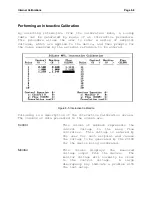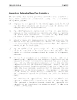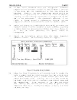
Internal Calibrations
Page 8-3
Linearization Methods
There are four linearization methods, independently selectable
for each calibrated device. The method to be used for a
particular device may be specified in the Device Parameters
screen, which can be selected from the device’s calibration menu.
The linearization methods available are described below. A
graphical comparison of these methods is shown in Figure 8-1.
Linear Fit
This method finds the best straight-line
fit to the calibration data. The linear
fit is best suited to very linear data.
Polynomial Fit
The polynomial fit, used in previous
versions of the software, finds the best
2
nd
order
polynomial
fit
to
the
calibration data and can compensate for
non-linearity in the data.
Lookup Table
This method uses the lookup table
directly and interpolates a straight
line
between
table
points.
By
definition,
this
technique
will
reproduce each calibration point exactly
(assuming perfect repeatability).
Spline Fit
This method uses a cubic spline to find
a smooth curve that passes through all
calibration points. As with the lookup
table, this technique guarantees that
calibration points will be reproduced
exactly,
but
is
more
likely
to
accurately
reproduce
data
between
calibration points.
If a lookup table has been generated for a device, any of the
four methods may be used. For the first two methods, polynomial
coefficients will be generated from the data in the lookup table
using regression techniques. Once the coefficients are known,
they can be entered manually rather than entering an entire data
table. The last two linearization methods require that a lookup
table be entered, either manually or during an interactive
calibration.
The default method used in factory calibrations for mass flow
controllers
and the optional UV photometer
is the
Lookup Table
.
The spline fit is the default method for the ozone generator.
Summary of Contents for 2010D
Page 1: ...MODEL 2010D GAS DILUTION CALIBRATOR OPERATIONS MANUAL I N S T R U M E N T S...
Page 3: ......
Page 20: ...System Operations Page 3 2 Figure 3 1 The Model 2010D Front Panel...
Page 42: ...Installation Page 4 15 Figure 4 1 Rear Panel...
Page 63: ...Operation Page 5 7 Figure 5 5 The Dilution Status Screen Figure 5 6 The Ozone Status Screen...
Page 177: ...MODEL 2010D GAS DILUTION CALIBRATOR SCHEMATICS...
Page 178: ......


