Internal Calibrations
Page 8-10
Interactively Calibrating Mass Flow Controllers
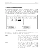
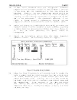
The following step-by-step procedure describes how to perform a
mass
flow
controller
calibration
using
the
interactive
calibration feature.
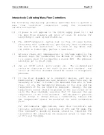
[1] If power is not applied to the
2010D
, apply power to it and
the mass flow standard and allow at least 30 minutes for
everything to warm up and stabilize.
[2] The
2010D
'
s pneumatic system must be free of leaks before
performing flow calibrations; particularly when calibrating
the source flow controllers. If there is any doubt that
the
2010D
is leak-tight, perform a leak test.
[3] Attach a clean, dry compressed air or nitrogen supply to the
diluent input for calibrating the diluent or ozone MFCs or
to a source input if calibrating a source MFC. The pressure
should be set to 20-25 PSIG.
[4] Cap all
2010D
outlet ports except one. The un-capped port
should be connected to the inlet of the flow standard. The
outlet of the flow standard should be vented to atmospheric
pressure.
[5] If the flow standard is a volumetric device, such as a
bubble-meter, temperature and pressure corrections may be
necessary in order to convert the measured flow rate to mass
flow. If so, the barometric pressure in the room and the
temperature of the gas should be measured. Ideally, the gas
temperature sensor should be placed in the gas stream as it
exits the flow standard, assuring that it measures the gas
temperature in the flow standard. The barometric pressure
is not likely to change during a calibration, however the
gas temperature should be measured for each calibration
point.
For environmental applications, mass flow controllers are
typically calibrated to conditions of 25°C and 760 mmHg. The
flow standard’s operating manual should be consulted for
instruction for converting its measured output to mass flow
at 25°C and 760 mmHg.
Summary of Contents for 2010D
Page 1: ...MODEL 2010D GAS DILUTION CALIBRATOR OPERATIONS MANUAL I N S T R U M E N T S...
Page 3: ......
Page 20: ...System Operations Page 3 2 Figure 3 1 The Model 2010D Front Panel...
Page 42: ...Installation Page 4 15 Figure 4 1 Rear Panel...
Page 63: ...Operation Page 5 7 Figure 5 5 The Dilution Status Screen Figure 5 6 The Ozone Status Screen...
Page 177: ...MODEL 2010D GAS DILUTION CALIBRATOR SCHEMATICS...
Page 178: ......


