Internal UV Ozone Photometer
Page 9-13
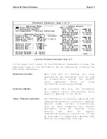
Below the Operating Modes section are the Operating Constants,
which govern the operation of the photometer and should not
normally be changed. Following are descriptions of these
parameters:
Sample Hold
The Sample Hold time is the number of
seconds
to
allow
after
the
sample/reference solenoid valves are
switched before detector readings are
taken. This time period is necessary in
order to allow the sample or reference
gas to fully fill the sample tube.
Sample Measure
The Sample Measure time is the number of
seconds of data to collect from the
detector after the Hold Time has elapsed
before switching the sample/reference
solenoid valves. The data collected
during this time is averaged in order to
reduce noise.
Lamp Setpoint
This is the voltage applied to the
Photometer's UV lamp drive. This should
be set to a value between 0 and 5 Volts
such that the detector output is between
the Detector Min and Detector Max during
the reference half of the Photometer
cycle.
Detector Offset and Gain
The Detector Gain and Offset parameters
are factory set to reflect resistor
values on the Lamp Drive Board that
cause
the
detector
signal
to
be
amplified and offset. These parameters
are needed in order to calculate the
ozone concentration and should not be
changed from their factory settings.
Detector Max and Min
The Detector Max and Min parameters
determine the range of the detector
signal that is considered acceptable.
Summary of Contents for 2010D
Page 1: ...MODEL 2010D GAS DILUTION CALIBRATOR OPERATIONS MANUAL I N S T R U M E N T S...
Page 3: ......
Page 20: ...System Operations Page 3 2 Figure 3 1 The Model 2010D Front Panel...
Page 42: ...Installation Page 4 15 Figure 4 1 Rear Panel...
Page 63: ...Operation Page 5 7 Figure 5 5 The Dilution Status Screen Figure 5 6 The Ozone Status Screen...
Page 177: ...MODEL 2010D GAS DILUTION CALIBRATOR SCHEMATICS...
Page 178: ......


