Operation
Page 5-10
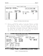
[6] The Source 1 MFC Control should now be highlighted. Enter
the calculated source flow value (e.g. 50 SCCM).
Though
the Source 1 MFC has been activated, no monitor flow will
be indicated until a source solenoid valve has been
activated.
[7] Press the F3 key, skipping the Ozone Temp field until the
Lamp Current field is highlighted. This is a value between
0 and 5 corresponding to the current applied to the ozone
generator's lamp.
Enter a value, for example 1.000, and
observe the calculated "Ozone Conc." control value. This
will indicate the ozone concentration that should be
produced based on the lamp current, the last ozone
generator calibration and the total flow rate.
Adjust the lamp current experimentally until the desired
ozone concentration is reached (e.g. 400 PPB). This is
done by backing up with the F2 (Shift-Tab) key and entering
different Lamp Current values until the calculated ozone is
showing the desired concentration.
[8] Press F3 until the source solenoid valve associated with
the gas cylinder containing Nitric Oxide (NO) is selected.
Press "1" or Space so that an "X" appears in the box. If a
pressurized gas source is attached, the Source 1 MFC
Monitor flow should now increase until it has approximately
matched the control value. A gas concentration determined
by the diluent and source flow rates, the source gas
concentration and the Ozone Generator Lamp Current will now
be produced by the
2010D
.
[9] To change concentrations or select a different gas, use the
F2 and F3 buttons (Shift-Tab and Tab) to move the cursor to
the appropriate field and then change the value.
[10] To stop the calibration, press the End Sequence button
until a box appears with Yes or No to abort the active
sequence. Select Yes and press the Enter button to stop
everything and return to a quiescent state.
Viewing Diagnostic Information
Occasionally, it is necessary to directly view the
2010D
's analog
or digital inputs or outputs. The "Diag" (Diagnostics) menu is
provided for this purpose.
There are four entries under the
Diag menu: Analog Inputs, Analog Outputs, Control Outputs and
Monitor I/O Bits. These diagnostic screens, which present the
data in real time, updated each second, are described in more
detail below.
Summary of Contents for 2010D
Page 1: ...MODEL 2010D GAS DILUTION CALIBRATOR OPERATIONS MANUAL I N S T R U M E N T S...
Page 3: ......
Page 20: ...System Operations Page 3 2 Figure 3 1 The Model 2010D Front Panel...
Page 42: ...Installation Page 4 15 Figure 4 1 Rear Panel...
Page 63: ...Operation Page 5 7 Figure 5 5 The Dilution Status Screen Figure 5 6 The Ozone Status Screen...
Page 177: ...MODEL 2010D GAS DILUTION CALIBRATOR SCHEMATICS...
Page 178: ......


