Serial Communications
Page 7-29
_________________________________________________________________
The Modbus Protocol
The Modbus protocol was developed by Modicon in the 70’s for
communicating with programmable logic controllers. Since then,
Modbus has become a de facto standard protocol that is typically
used for connecting industrial devices to computers. Modbus is
a master/slave protocol that comes in three major flavors:
RTU – A binary protocol that utilizes an idle time in
transmission to recognize the start of a command packet
ASCII – Each command starts with a “:” character and the
data is presented as ASCII characters in hexadecimal
format
TCP – A variation of the Modbus protocol designed for
transmission over TCP/IP networks
Modbus operates by reading and writing “coils” and “registers”.
Coils are individual on/off controls or sensors, such as valves
or digital IO bits. Registers contain numeric values, such as
flows, pressures or concentrations. More information about the
Modbus protocol can be found at
www.modbus.org
.
Sabio’s implementation of Modbus Maps the coils and registers
for compatibility with the API calibrator. Other mappings are
available upon request.
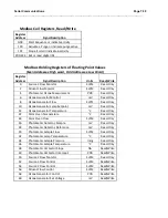
Modbus Discreet Input Registers
Register
Address
Signal Description
0
Reset flag
1
Enclosure Temperature
2
Photometer Lamp Temp Alarm
3
Ozone Generator Temp Alarm
4
Perm Oven 1 Temp Alarm
5
Photometer Reference Alarm
6
Photometer Lamp Error
7
Ozone Generator Monitor Alarm
10
MFC Setpoint Alarm
11
MFC Monitor Alarm
12
Dilution Comm Error
13
Photometer Comm Error
19
No Alarms
20
Ozone Generator Warmup
21
Perm Oven 2 Temp Alarm
Summary of Contents for 2010D
Page 1: ...MODEL 2010D GAS DILUTION CALIBRATOR OPERATIONS MANUAL I N S T R U M E N T S...
Page 3: ......
Page 20: ...System Operations Page 3 2 Figure 3 1 The Model 2010D Front Panel...
Page 42: ...Installation Page 4 15 Figure 4 1 Rear Panel...
Page 63: ...Operation Page 5 7 Figure 5 5 The Dilution Status Screen Figure 5 6 The Ozone Status Screen...
Page 177: ...MODEL 2010D GAS DILUTION CALIBRATOR SCHEMATICS...
Page 178: ......


