Internal UV Ozone Photometer
Page 9-15
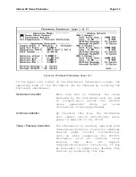
The second page of the Photometer Parameters, shown in Figure 9-
contains scaling factors for the various sensors associated with
the photometer. For each sensor, there is a sensor equation (and
a control equation for the Lamp Temperature) that allows the
sensor to be calibrated precisely by setting the three polynomial
coefficients. Note that if the C coefficient is set to zero, the
A and B coefficients will correspond to the intercept and slope,
respectively, of a simple linear equation. With the exception of
the sample flow, the Photometer's sensors are very linear.
Of these sensors, the Sample Temperature and Pressure are the
most critical, since they are used to compensate the ozone
measured by the Photometer for temperature and pressure
variations. The Lamp Temperature and Sample Flow are provided as
diagnostic tools.
Figure 9-7 Photometer Parameters, Page 2 of 3
Following are brief descriptions of the various sensors:
Lamp Temperature
The setpoint, high and low alarms and
the sensor and control equations may be
altered in this section. Ordinarily it
is not necessary to change these
parameters.
Summary of Contents for 2010D
Page 1: ...MODEL 2010D GAS DILUTION CALIBRATOR OPERATIONS MANUAL I N S T R U M E N T S...
Page 3: ......
Page 20: ...System Operations Page 3 2 Figure 3 1 The Model 2010D Front Panel...
Page 42: ...Installation Page 4 15 Figure 4 1 Rear Panel...
Page 63: ...Operation Page 5 7 Figure 5 5 The Dilution Status Screen Figure 5 6 The Ozone Status Screen...
Page 177: ...MODEL 2010D GAS DILUTION CALIBRATOR SCHEMATICS...
Page 178: ......


