6 Troubleshooting
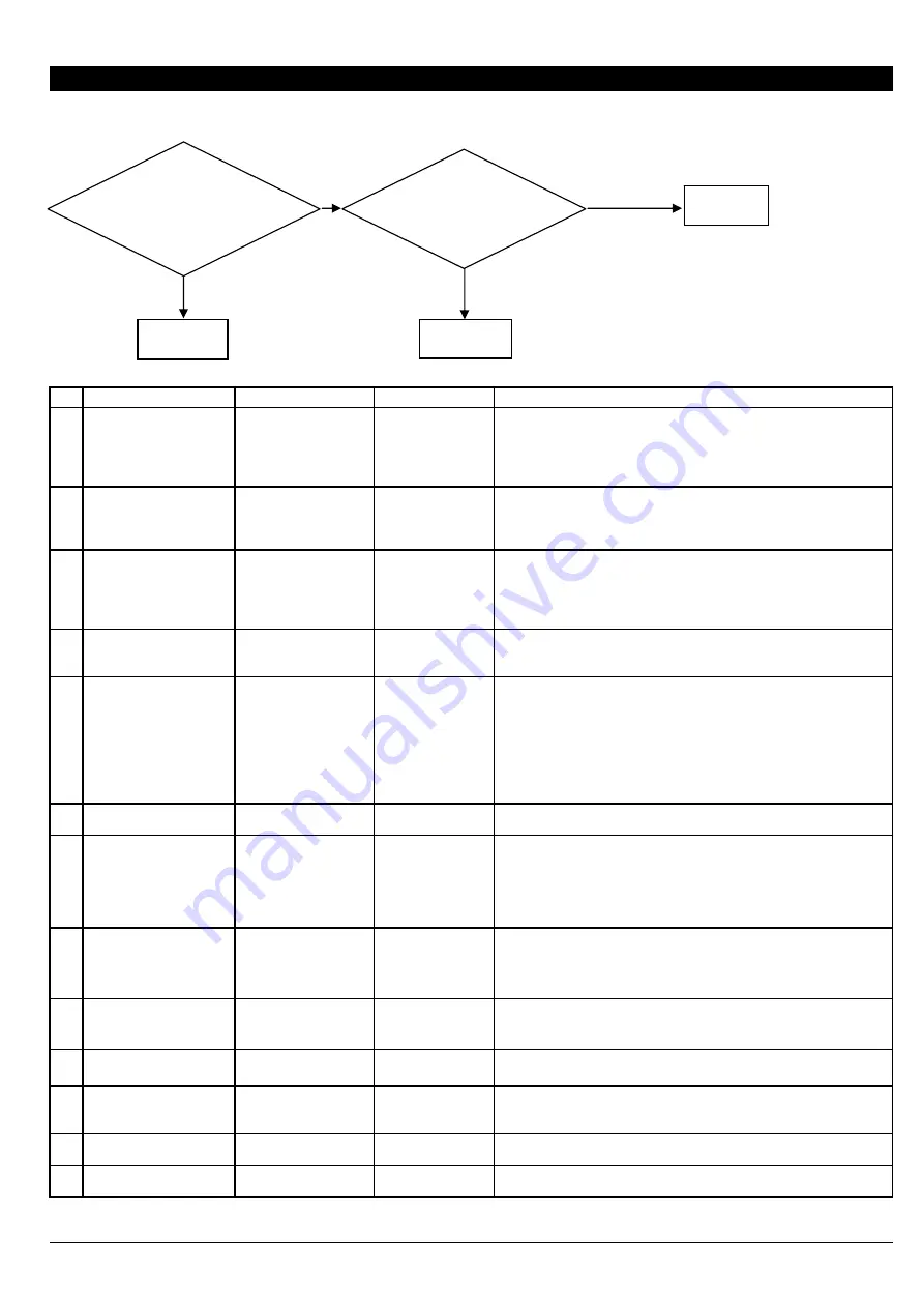
6-1 WHITE FINE LINE / BANDING / MISSING DOT / SCRATCHY PRINTING / BLURRED PRINTING
NO
CHECKING POINT
ACTION
REFERENCE
OUTLINE
1
The loaded media in width
is below 1220 mm
Replace the media in
width more than 1220
mm
When the loaded media is short, it may not be tensioned equally at
both ends because the Dancer Roller is out of the horizontal . In
addition, the cooling effect caused by fans is increased and it lowers
the heater temperature. As a result, banding or the like appears.
2
The media is not loaded
and set up correctly
Load and set up the
media correctly
Loading media at a position where its left and right edges are
unbalanced may result in white fine line or banding in the printing
image. Reload the media onto the roll shaft so that the left and right
margins are the same using the media gauge.
3
The temperature of
Preheater/Print heater is
too high
Apply correct setting
User's Manual
The optimal temperature for the media heating system varies
according to the type of media and the print mode. The temperature of
Preheater/Print heater is too high may cause the white banding
because the landed dot may dry off before it expands to the proper
size.
4
The heater has not
warmed up
Check whether each
setting is correct
[6-10 HEATER
TEMPERATURE
DOES NOT GO UP]
Check whether each setting is correct referring to the above [6-10
HEATER TEMPERATURE DOES NOT GO UP].
5
The media is not warm
enough
Increase the preset
temperature
Check the room
temperature
Wait for a while until
media warms up
When media is not heated sufficiently, the ink may dry unevenly or
collect unevenness could happen.
Even if the heater reaches the setting temperature, when the media
has got cold, even if the temperature of a heater reaches the setting
value, an effect may not appear.
Warm up the media fully taming to the room temperature of 20-32
degree °C and wait about 5 minutes after the heater reaches the
setting temperature or raising setting temperature etc.
6
CALIBRATION for feeding
direction is not correct
Calibration
User's Manual
If the calibration is not correct, white fine line or banding appears.
7
The back tension on the
loaded media is too
strong.
Pre-feed the media
sheet once and reroll it
again
The banding of overlap and gap may appear on the media with
adhesive because the Feed Dancer Roller cannot maintain uniform
tension for the feed media. You can remove the adhesive from the
media by pre-feeding the media and rerolling it again.
8
Movement width of the
printing carriage
Set the [FULL WIDTHS]
to [FULL]
User's Manual
Set [FULL WIDTHS] to [FULL] to uniform the heating time on each
path. This may improve printing quality.
9
[PERIODIC CL.] setting
Set [PERIODIC CL.] to
[NONE] or [Page]
User's Manual
When this is set to a value from 1 min to 99 min, self cleaning is
performed during printing and it may cause of blurred printing.
10
Wrong profile for the
media
Use the suitable profile
11
Wrong media is used
Replace to the suitable
media
The amount of ink which can be held changes with the media type.
Depending on the media, the ink may not be applied, but may overflow
or blur.
12
Head Rank is incorrect
Set Head Rank
[3-1 HEAD
REPLACEMENT]
Head rank setting affects the amount of the fired ink. If it is not set
properly, the printing image becomes light, dark or blurred.
13
Head is out of adjustment Head Alignment
[4-4 HEAD
ALIGNMENT]
Check whether each [BIAS], [VERTICAL], [HORIZONTAL] and [BI-
DIR.DEFAULT] setting is correct.
6-1
Missing dot or
deflected-fired dot
appears on the test
pattern.
Perform Normal
Cleaning
Completed
To 14-20
To 1-13
Yes
No
Improved
Not Improved
*Several Normal Cleanings and a
Powerful Cleaning do not improve the
printing result.
Summary of Contents for Advanced Jet AJ-1000
Page 2: ...Revision NO Date Description of Changes Approval Issued 0 2006 7 4 First Edition Kato Mabuchi ...
Page 43: ...2 12 Arrangement Diagram_ Soldering Side ...
Page 51: ...2 20 Arrangement Diagram_ Soldering Side ...
Page 58: ...2 27 It indicates the version of the Heater Board ...
Page 66: ...2 35 It indicates the version of the Pump Drive Board ...
Page 74: ...2 43 It indicates the version of the Sub Board ...
Page 75: ...2 44 CN302 Arrangement Diagram_ Soldering Side ...
Page 76: ...2 45 U650 U700 U750 CN800 CN60 0 ...
Page 288: ......


