Chapter 2: Connecting External Equipment (Optional)
54
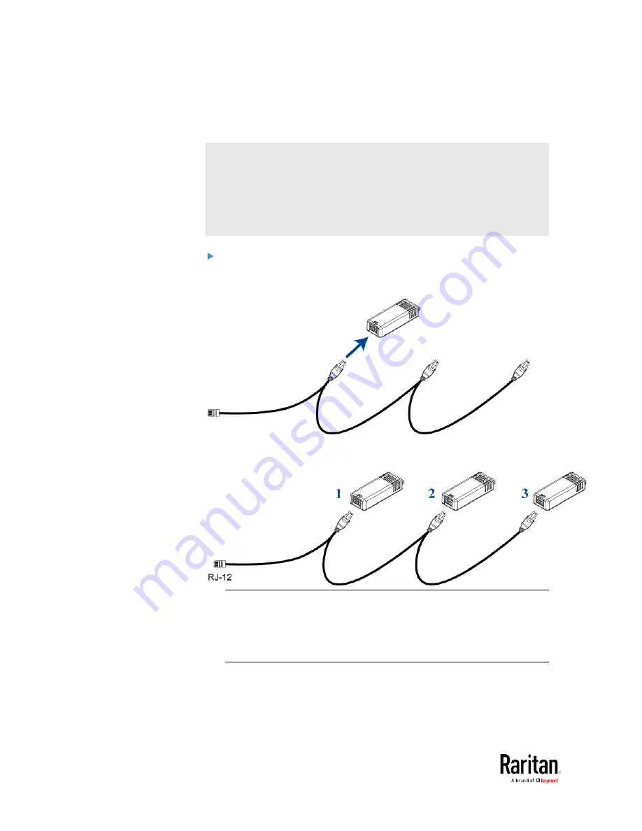
The following procedure illustrates a DPX2 sensor cable with three head
connectors. Your sensor cable may have fewer head connectors.
Warning: If there are free head connectors between a DPX2 sensor
cable's RJ-12 connector and the final attached DPX2 sensor package,
the sensor packages following the free head connector(s) on the same
cable do NOT work properly. Therefore, always occupy all head
connectors prior to the final sensor package with a DPX2 sensor
package.
To connect DPX2 sensor packages to the BCM2:
1.
Connect a DPX2 sensor package to the first head connector of the
DPX2 sensor cable.
2.
Connect remaining DPX2 sensor packages to the second and then
the third head connector.
Tip: If the number of sensors you are connecting is less than the
number of head connectors on your sensor cable, connect them to
the first one or first two head connectors to ensure that there are NO
free head connectors prior to the final DPX2 sensor package
attached.
3.
Use an RJ-12 to RJ-45 adapter to connect the DPX2 sensor
package(s) to the BCM2.
a.
Connect the adapter's RJ-12 connector to the DPX2 sensor
cable.
Summary of Contents for PMC-1000
Page 3: ...BCM2 Series Power Meter Xerus Firmware v3 4 0 User Guide...
Page 23: ...Chapter 1 Installation and Initial Configuration 11 Panel Wiring Example...
Page 54: ...Chapter 1 Installation and Initial Configuration 42 Branch Circuit Details...
Page 76: ...Chapter 2 Connecting External Equipment Optional 64...
Page 123: ...Chapter 3 Using the Web Interface 111...
Page 558: ...Appendix D RADIUS Configuration Illustration 546 Note If your BCM2 uses PAP then select PAP...
Page 563: ...Appendix D RADIUS Configuration Illustration 551 14 The new attribute is added Click OK...
Page 564: ...Appendix D RADIUS Configuration Illustration 552 15 Click Next to continue...
Page 594: ...Appendix E Additional BCM2 Information 582...
Page 612: ......


