Chapter 3: Using the Web Interface
138
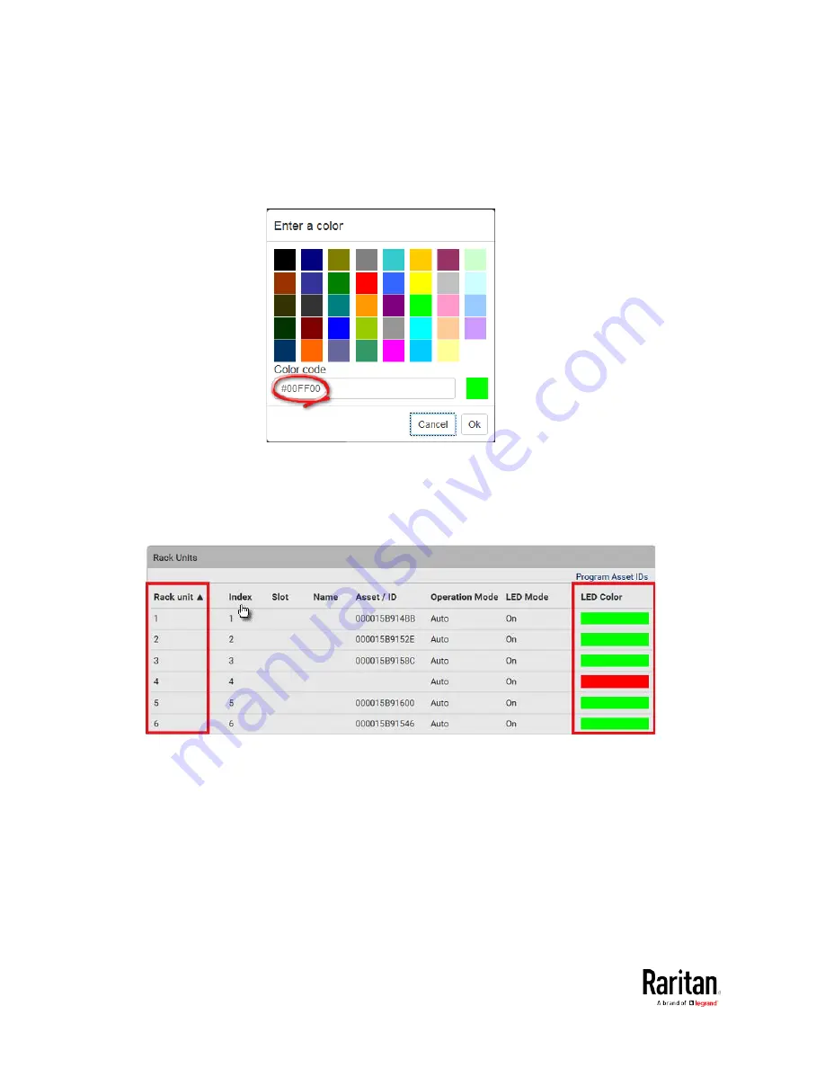
For color settings, there are two ways to set the color.
Click a color in the color palette.
Type the hexadecimal RGB value of the color, such as #00FF00.
3.
Click Ok. The rack unit numbering and LED color settings are
immediately updated on the Rack Units list illustrated below.
The 'Index' number is the physical tag port number printed on
the asset strip, which is not configurable. However, its order will
change to reflect the latest rack unit numbering.
A blade extension strip and a
programmable tag are marked with
the word 'programmable' in the Asset/ID column. You can
customize their Asset IDs. For instructions, refer to this
section's last procedure below.
If wanted, you can resort the list by clicking the desired column
header. See Sorting a List.
Summary of Contents for PMC-1000
Page 3: ...BCM2 Series Power Meter Xerus Firmware v3 4 0 User Guide...
Page 23: ...Chapter 1 Installation and Initial Configuration 11 Panel Wiring Example...
Page 54: ...Chapter 1 Installation and Initial Configuration 42 Branch Circuit Details...
Page 76: ...Chapter 2 Connecting External Equipment Optional 64...
Page 123: ...Chapter 3 Using the Web Interface 111...
Page 558: ...Appendix D RADIUS Configuration Illustration 546 Note If your BCM2 uses PAP then select PAP...
Page 563: ...Appendix D RADIUS Configuration Illustration 551 14 The new attribute is added Click OK...
Page 564: ...Appendix D RADIUS Configuration Illustration 552 15 Click Next to continue...
Page 594: ...Appendix E Additional BCM2 Information 582...
Page 612: ......


