Chapter 3: Using the Web Interface
261
a.
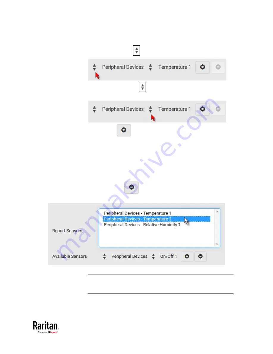
Click the first
to select a target component from the list.
b.
Click the second
to select the specific sensor for the target
from the list.
c.
Click
to add the selected sensor to the Report Sensors
list box.
For example, to monitor the current reading of the Inlet 1, select
Inlet 1 from the left field, and then select RMS Current from the right
field.
5.
To report additional sensors simultaneously, repeat the above step
to add more sensors.
To remove any sensor from the Report Sensors list box, select it
and click
. To make multiple selections, press Ctrl+click
or Shift+click to highlight multiple ones.
6.
To immediately send out the sensor report, click Send Report Now.
Tip: When intending to send a sensor report using custom messages,
use the placeholder [SENSORREPORT] to report sensor readings. See
Placeholders for Custom Messages
(on page 276).
Summary of Contents for PMC-1000
Page 3: ...BCM2 Series Power Meter Xerus Firmware v3 4 0 User Guide...
Page 23: ...Chapter 1 Installation and Initial Configuration 11 Panel Wiring Example...
Page 54: ...Chapter 1 Installation and Initial Configuration 42 Branch Circuit Details...
Page 76: ...Chapter 2 Connecting External Equipment Optional 64...
Page 123: ...Chapter 3 Using the Web Interface 111...
Page 558: ...Appendix D RADIUS Configuration Illustration 546 Note If your BCM2 uses PAP then select PAP...
Page 563: ...Appendix D RADIUS Configuration Illustration 551 14 The new attribute is added Click OK...
Page 564: ...Appendix D RADIUS Configuration Illustration 552 15 Click Next to continue...
Page 594: ...Appendix E Additional BCM2 Information 582...
Page 612: ......


