


Chapter 3: Using the Web Interface
285
2.
In this illustration, assign the name "Contact Closure Triggered Load
Shedding" to the new rule.
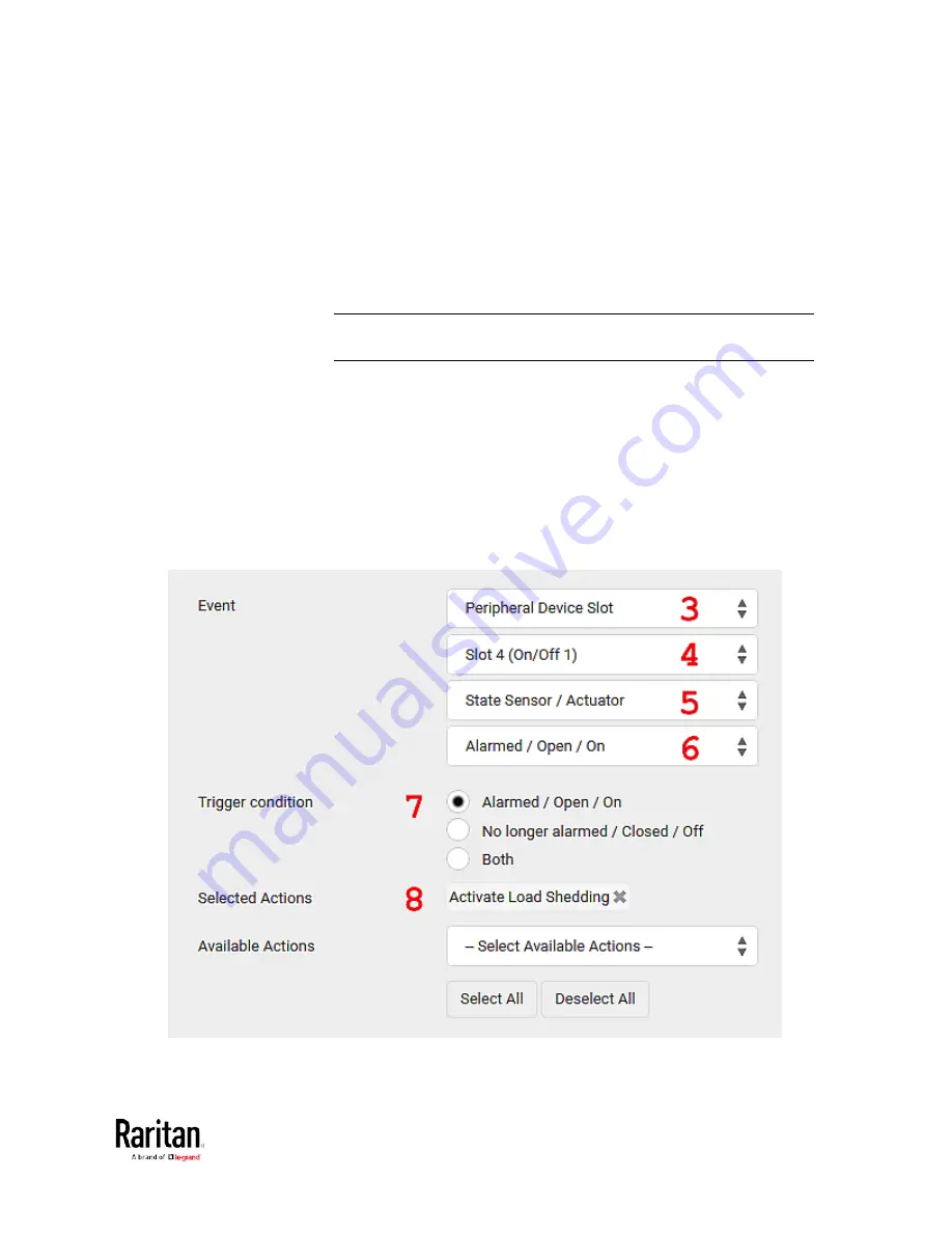
3.
In the Event field, select "Peripheral Device Slot" to indicate we are
specifying an event related to the environmental sensor package.
4.
Select the ID number of the desired contact closure sensor. In this
illustration, the ID number of the desired contact closure sensor is 1,
so select Slot 1.
Note: ID numbers of all sensors/actuators are available on the
Peripherals page. See
Peripherals
(on page 115).
5.
Select "State Sensor/Actuator" because the contact closure sensor
is a state sensor.
6.
Select "Alarmed" since we want the BCM2 to respond when the
selected contact closure sensor changes its state related to the
"alarmed" state.
7.
In the "Trigger condition" field, select the Alarmed/Open/On radio
button so that the action is taken only when the contact closure
sensor enters the alarmed state.
8.
Select "Activate Load Shedding" from the Available Actions list.
Summary of Contents for PMC-1000
Page 3: ...BCM2 Series Power Meter Xerus Firmware v3 4 0 User Guide...
Page 23: ...Chapter 1 Installation and Initial Configuration 11 Panel Wiring Example...
Page 54: ...Chapter 1 Installation and Initial Configuration 42 Branch Circuit Details...
Page 76: ...Chapter 2 Connecting External Equipment Optional 64...
Page 123: ...Chapter 3 Using the Web Interface 111...
Page 558: ...Appendix D RADIUS Configuration Illustration 546 Note If your BCM2 uses PAP then select PAP...
Page 563: ...Appendix D RADIUS Configuration Illustration 551 14 The new attribute is added Click OK...
Page 564: ...Appendix D RADIUS Configuration Illustration 552 15 Click Next to continue...
Page 594: ...Appendix E Additional BCM2 Information 582...
Page 612: ......


