Chapter 2: Connecting External Equipment (Optional)
69
3.
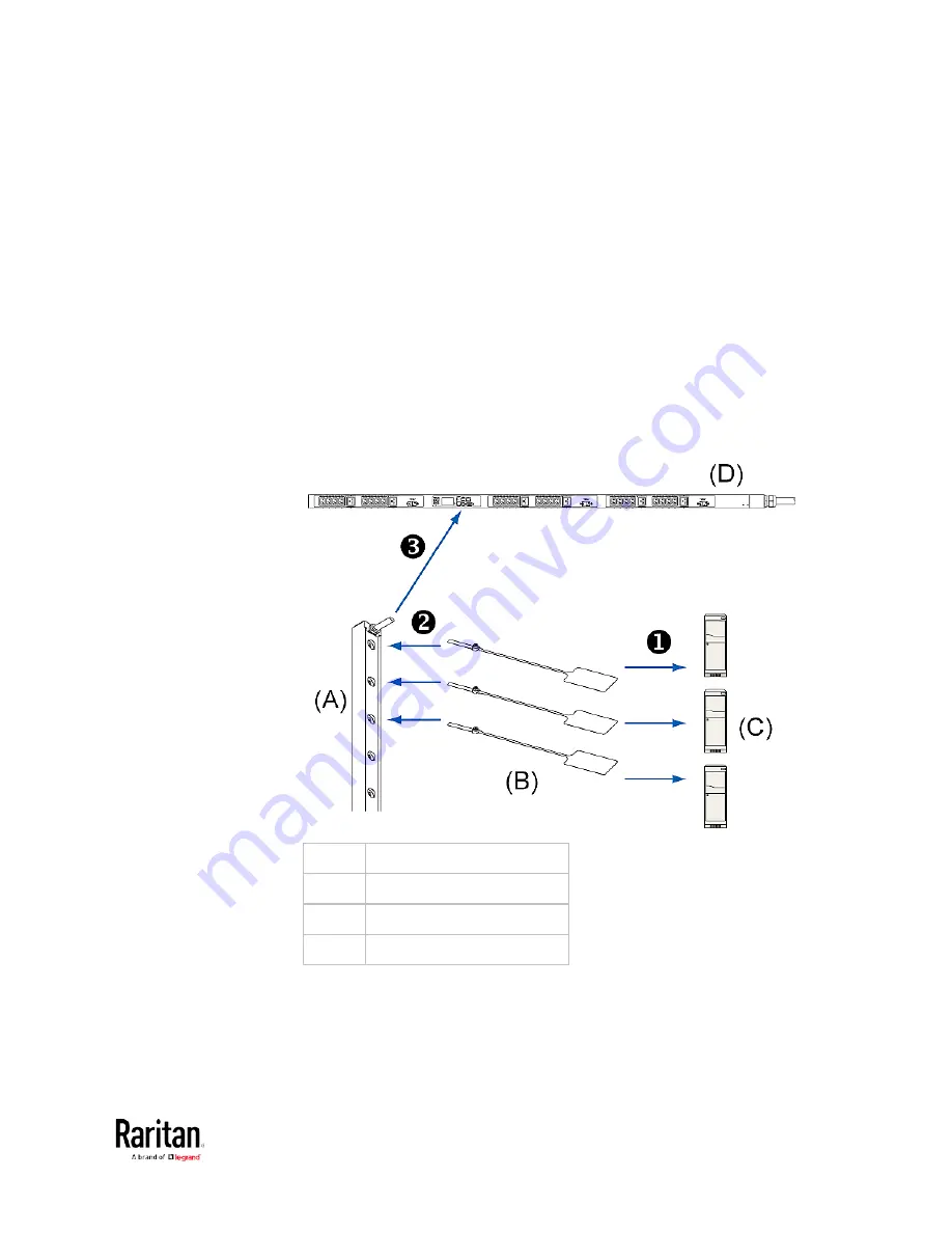
Connect the asset strip assembly to the BCM2 device, using a
network patch cable (CAT5e or higher).
Connect one end of the cable to the RJ-45 connector on the
MASTER asset strip.
Connect the other end of the cable to the FEATURE port on the
BCM2 device.
The BCM2 device supplies power to the connected asset strip
assembly. All LEDs on the asset strip assembly may cycle through
different colors during the power-on process if the asset strip's
firmware is being upgraded by the BCM2. After the power-on or
firmware upgrade process completes, the LEDs show solid colors.
Note that the LED color of the tag ports with asset tags connected
will be different from the LED color of the tag ports without asset
tags connected.
(A)
MASTER asset strip
(B)
Asset tags
(C)
IT devices
(D)
BCM2
Summary of Contents for PMC-1000
Page 3: ...BCM2 Series Power Meter Xerus Firmware v3 4 0 User Guide...
Page 23: ...Chapter 1 Installation and Initial Configuration 11 Panel Wiring Example...
Page 54: ...Chapter 1 Installation and Initial Configuration 42 Branch Circuit Details...
Page 76: ...Chapter 2 Connecting External Equipment Optional 64...
Page 123: ...Chapter 3 Using the Web Interface 111...
Page 558: ...Appendix D RADIUS Configuration Illustration 546 Note If your BCM2 uses PAP then select PAP...
Page 563: ...Appendix D RADIUS Configuration Illustration 551 14 The new attribute is added Click OK...
Page 564: ...Appendix D RADIUS Configuration Illustration 552 15 Click Next to continue...
Page 594: ...Appendix E Additional BCM2 Information 582...
Page 612: ......


