


Chapter 2: Connecting External Equipment (Optional)
55
b.
Connect the adapter's RJ-45 connector to the RJ-45 SENSOR
port of the BCM2.
OR you can directly connect the DPX2 sensor package to a DX sensor
chain without using any RJ-12 to RJ-45 adapter. See
Connecting a
DPX2 Sensor Package to DX
(on page 59).
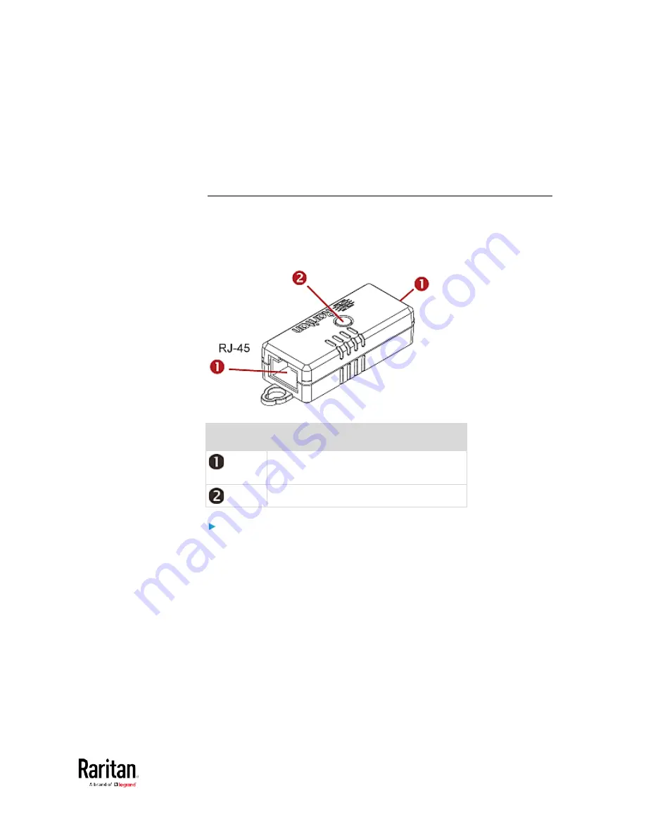
DPX3 Sensor Packages
A DPX3 sensor package features the following:
•
Its connection interface is RJ-45.
•
You can cascade a maximum of 12 DPX3 sensor packages.
Numbers Components
RJ-45 ports, each of which is located on
either end of a DPX3 sensor package.
LED for indicating the sensor status.
To connect DPX3 sensor packages to the BCM2:
1.
Connect a standard network patch cable (CAT5e or higher) to either
RJ-45 port on the DPX3 sensor package.
2.
If you want to cascade DPX3 sensor packages, get an additional
standard network patch cable (CAT5e or higher) and then:
a.
Plug one end of the cable into the remaining RJ-45 port on the
prior DPX3.
b.
Plug the other end into either RJ-45 port on an additional DPX3.
Summary of Contents for PMC-1000
Page 3: ...BCM2 Series Power Meter Xerus Firmware v3 4 0 User Guide...
Page 23: ...Chapter 1 Installation and Initial Configuration 11 Panel Wiring Example...
Page 54: ...Chapter 1 Installation and Initial Configuration 42 Branch Circuit Details...
Page 76: ...Chapter 2 Connecting External Equipment Optional 64...
Page 123: ...Chapter 3 Using the Web Interface 111...
Page 558: ...Appendix D RADIUS Configuration Illustration 546 Note If your BCM2 uses PAP then select PAP...
Page 563: ...Appendix D RADIUS Configuration Illustration 551 14 The new attribute is added Click OK...
Page 564: ...Appendix D RADIUS Configuration Illustration 552 15 Click Next to continue...
Page 594: ...Appendix E Additional BCM2 Information 582...
Page 612: ......


