


3-19
3-1 Servo Drive Specifications
OMNUC G5-Series AC Servo Drives Users Manual (Built-in MECHATROLINK-II communications type)
3
Specifications
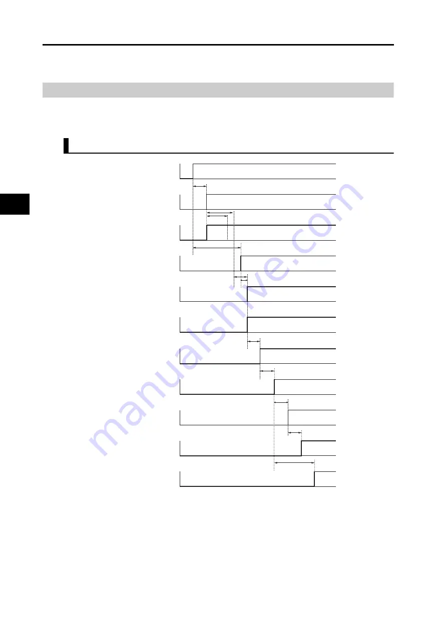
Control Output Details
The chart below illustrates the timings of the command inputs after the control power-on. Enter
the Servo ON, and the position, speed or torque command in the correct timing as shown in
the chart.
Control Output Sequence
*1. Once the internal control power is established, the protective function starts working about 1.5 s after the MPU starts
initializing itself. Be sure that all I/O signals that are connected to the Servo Drive, especially the Forward/Reverse
Drive Prohibition Input (POT/NOT), the Origin Proximity Input (DEC), the external encoder input, are settled before
the protective function starts working. The period can be extended by the Power Supply ON Initialization Time
(Pn618).
*2. The Servo ready completed output (READY) turns ON only when all of these conditions are met: The MPU
initialization is completed. The Main power is established. No alarm exists. MECHATROLINK-II communications are
established. The servo is synchronized (Phase alignment).
*3. The Brake Interlock Output (BKIR) turns ON when the OR condition is met: a release request by the servo control
and by the MECHATROLINK-II communications.
*4. During this period, the Servo ON signal is input on the hardware, but it is not processed.
Control power supply
(L1C and L2C)
Internal control
power supply
MPU initialization
completed
Main circuit power
supply
(L1, L2 and L3)
Servo ready
completed output
(READY)
Alarm output
(/ALM)
ON
OFF
ON
OFF
ON
OFF
ON
OFF
ON
OFF
ON
OFF
Approx. 100 to 300 ms
Approx. 2 s
Approx. 1.5 s
Iinitialization
*1
Approx. 10 ms after initialization
and main circuit ON
*2
Servo ON input
Dynamic brake
Motor power supply
Brake interlock
output (BKIR)
*3
Position, speed or
torque command
ON
OFF
ON
OFF
ON
OFF
ON
OFF
ON
OFF
Approx. 60 ms
Approx. 2 ms
Approx. 4 ms
0 ms or more
0 s or more
100 ms or
more
*4


