


3. Enable error interrupts in the EEI register if so desired.
4. Write the 32-byte TCD for each channel that may request service.
5. Enable any hardware service requests via the ERQ register.
6. Request channel service via either:
• Software: setting the TCDn_CSR[START]
• Hardware: slave device asserting its eDMA peripheral request signal
After any channel requests service, a channel is selected for execution based on the
arbitration and priority levels written into the programmer's model. The eDMA engine
reads the entire TCD, including the TCD control and status fields, as shown in the
following table, for the selected channel into its internal address path module.
As the TCD is read, the first transfer is initiated on the internal bus, unless a
configuration error is detected. Transfers from the source, as defined by TCDn_SADDR,
to the destination, as defined by TCDn_DADDR, continue until the number of bytes
specified by TCDn_NBYTES are transferred.
When the transfer is complete, the eDMA engine's local TCDn_SADDR,
TCDn_DADDR, and TCDn_CITER are written back to the main TCD memory and any
minor loop channel linking is performed, if enabled. If the major loop is exhausted,
further post processing executes, such as interrupts, major loop channel linking, and
scatter/gather operations, if enabled.
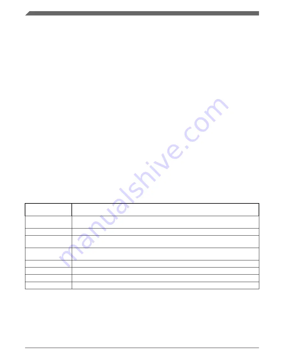
Table 12-8. TCD Control and Status fields
TCDn_CSR field
name
Description
START
Control bit to start channel explicitly when using a software initiated DMA service (Automatically
cleared by hardware)
ACTIVE
Status bit indicating the channel is currently in execution
DONE
Status bit indicating major loop completion (cleared by software when using a software initiated
DMA service)
D_REQ
Control bit to disable DMA request at end of major loop completion when using a hardware initiated
DMA service
BWC
Control bits for throttling bandwidth control of a channel
E_SG
Control bit to enable scatter-gather feature
INT_HALF
Control bit to enable interrupt when major loop is half complete
INT_MAJ
Control bit to enable interrupt when major loop completes
The following figure shows how each DMA request initiates one minor-loop transfer, or
iteration, without CPU intervention. DMA arbitration can occur after each minor loop,
and one level of minor loop DMA preemption is allowed. The number of minor loops in
a major loop is specified by the beginning iteration count (BITER).
Initialization/application information
Kinetis KE1xF Sub-Family Reference Manual, Rev. 4, 06/2019
292
NXP Semiconductors
Summary of Contents for KE1xF Series
Page 2: ...Kinetis KE1xF Sub Family Reference Manual Rev 4 06 2019 2 NXP Semiconductors...
Page 138: ...Usage Guide Kinetis KE1xF Sub Family Reference Manual Rev 4 06 2019 138 NXP Semiconductors...
Page 360: ...Usage Guide Kinetis KE1xF Sub Family Reference Manual Rev 4 06 2019 360 NXP Semiconductors...
Page 490: ...Interrupts Kinetis KE1xF Sub Family Reference Manual Rev 4 06 2019 490 NXP Semiconductors...
Page 562: ...Boot Kinetis KE1xF Sub Family Reference Manual Rev 4 06 2019 562 NXP Semiconductors...
Page 706: ...Usage Guide Kinetis KE1xF Sub Family Reference Manual Rev 4 06 2019 706 NXP Semiconductors...
Page 736: ...Usage Guide Kinetis KE1xF Sub Family Reference Manual Rev 4 06 2019 736 NXP Semiconductors...
Page 866: ...Usage Guide Kinetis KE1xF Sub Family Reference Manual Rev 4 06 2019 866 NXP Semiconductors...
Page 1164: ...Usage Guide Kinetis KE1xF Sub Family Reference Manual Rev 4 06 2019 1164 NXP Semiconductors...
Page 1178: ...Usage Guide Kinetis KE1xF Sub Family Reference Manual Rev 4 06 2019 1178 NXP Semiconductors...
Page 1380: ...Usage Guide Kinetis KE1xF Sub Family Reference Manual Rev 4 06 2019 1380 NXP Semiconductors...
Page 1472: ...Kinetis KE1xF Sub Family Reference Manual Rev 4 06 2019 1472 NXP Semiconductors...
Page 1482: ...Kinetis KE1xF Sub Family Reference Manual Rev 4 06 2019 1482 NXP Semiconductors...