background image

Configuring Your Server    4-17

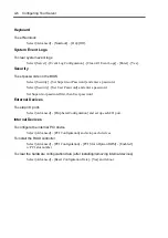
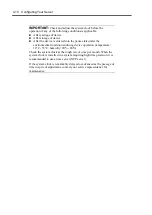
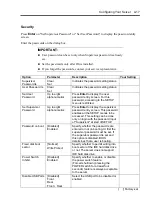
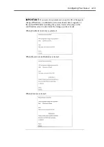
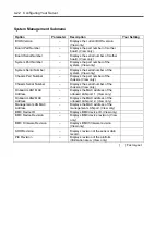
Security

Press 

Enter

 on "Set Supervisor Password" or "Set User Password," to display the password entry

screen.

Enter the passwords on the dialog box.

IMPORTANT:

„


User password can be set only when Supervisor password is already
set.

„


Set the passwords only after OS is installed.

„


If you forget the passwords, contact your service representative.

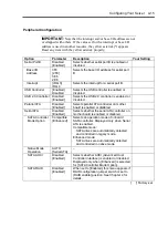
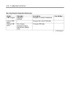
Option

Parameter

Description

Your Setting

Supervisor
Password Is

Clear
Set

Indicates the password setting status.

User Password Is

Clear
Set

Indicates the password setting status.

Set User
Password

Up to eight
alphanumerics

Press 

Enter

 to display the user

password entry screen. For this
password, accessing to the SETUP
menu is restricted.

Set Supervisor
Password

Up to eight
alphanumerics

Press 

Enter

 to display the supervisor

password entry screen. This password
enables all the SETUP menus to be
accessed. This setting can be done
only on login with the password input
of "Supervisor" at start of SETUP.

Password on boot

[Disabled]
Enabled

Specify whether the passwords are
entered or not on booting. At first the
supervisor password must be set. If
the supervisor password is set and
this option is disabled, BIOS
determines that a user is booting.

Fixed disk boot
sector

[Normal]
Write Protect

Specify whether to permit writing into
boot sector of the IDE hard disk drive
or not. The server does not support
IDE hard disk drive.

Power Switch

Inhibit

[Disabled]

Enabled

Specify whether to enable or disable
the power switch feature.
(Forced shutdown (pressing the
POWER switch for at least four
seconds) feature is always acceptable
to the server.

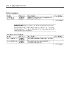
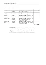
Disable USB Ports

[Disabled]
Front
Rear
Front + Rear

Select the USB port to be disabled or
enabled.

[   ]: Factory-set

Summary of Contents for N8100-14522F

Page 1: ...N8100 1452F 1453F NEC Express5800 i120Ra e1 User s Guide 1st Edition 6 2008 ONL 510_007_02 i120Ra e1 000 99 0806...

Page 2: ...e Warranty Statement accompanying each product However actual performance of each such product is dependent upon factors such as system configuration customer data and operator control Since implement...

Page 3: ...cause minor personal injury including burns or property damage if the instruction is ignored Precautions and notices against hazards are presented with one of the following three symbols The individua...

Page 4: ...Indicates a general notice or warning that cannot be specifically identified Prohibited Actions Indicates a general prohibited action that cannot be specifically identified Do not disassemble repair...

Page 5: ...n accordance with the instruction manual may cause harmful interference to radio communications Operation of this equipment in a residential area is likely to cause harmful interference in which case...

Page 6: ...r 2003 stands for Microsoft Windows Server 2003 R2 Standard Edition operating system and Microsoft Windows Server 2003 R2 Enterprise Edition operating system or Microsoft Windows Server 2003 Standard...

Page 7: ...ase of this server is your assurance of receiving state of the art high quality hardware to meet your needs both now and in the future Read this User s Guide thoroughly to fully understand handling of...

Page 8: ...to configure the system and provides instructions for running the BIOS SETUP Utility and the RAID configuration utility which is used to configure RAID drives in your system This chapter also provide...

Page 9: ...tions The following conventions are used throughout this manual For safety symbols see SAFETY INDICATIONS provided earlier IMPORTANT Items that are mandatory or require attention when using the server...

Page 10: ...12 Transfer to Third Party 1 13 Disposal and Consumables 1 14 User Support 1 15 Chapter 2 General Description 2 1 Overview 2 2 System Chassis 2 3 Front View 2 3 Rear View 2 5 Internal View 2 6 Mother...

Page 11: ...RAID System Configuration 4 28 RAID 4 28 Configuration by Onboard RAID Controller 4 33 Setup Utility 4 35 LSI Software RAID Configuration Utility and Universal RAID Utility 4 48 Configuring Mother Bo...

Page 12: ...1 Making Backup Copies 7 1 Cleaning 7 2 Cleaning the Server 7 3 Cleaning the Interior 7 4 Cleaning the Keyboard Mouse 7 5 Cleaning Disc 7 6 System Diagnostics 7 7 Test Items 7 7 Startup and Exit of S...

Page 13: ...ons and Windows Server 2003 8 31 Maintenance Tools 8 32 Starting Maintenance Tools 8 32 Function of Maintenance Tools 8 34 Maintenance Tools with Remote Console 8 36 Resetting the Server 8 38 Forced S...

Page 14: ...for EXPRESSBUILDER D 5 Windows Server 2003 x64 Editions Clean Installation D 7 Reinstallation to Multiple Logical Drives D 9 Procedure for License Authentication D 10 Updating the System Applying Serv...

Page 15: ...ion to Multiple Logical Drives E 11 Re installing the Operation System if Multiple Logical Drives Exist E 13 Procedure for License Authentication E 14 Updating the System Applying Service Pack E 14 Dr...

Page 16: ...x This page is intentionally left blank...

Page 17: ...Chapter 1 Notes on Using Your Server This chapter includes information necessary for proper and safe operation of your server...

Page 18: ...their vicinity in your server to inform the user that a hazardous situation may arise when operating the server Do not intentionally remove or damage any of the labels If you find any labels totally p...

Page 19: ...needles or metal objects into ventilation holes in the server or openings in the floppy disk or optical disk drive Doing so may cause an electric shock Do not use the server in any unapproved place I...

Page 20: ...eign matter e g pins or paper clips enter the server Failure to follow this warning may cause an electric shock a fire or a failure of the server When such things accidentally enter the server immedia...

Page 21: ...trays for the rack Failure to follow this instruction may cause some parts to fall to be broken and or to result in personal injury Insert hinges completely When installing the rack door make sure tha...

Page 22: ...fications of your server may heat up the cord and cause a fire Do not connect the power cord to an outlet that has an illegal number of connections The electric current exceeding the rated flow overhe...

Page 23: ...the power cord Do not place any object on the power cord Do not bundle power cords Do not alter modify or repair the power cord Do not secure the power cord with staples or equivalents Do not use any...

Page 24: ...dium chloride or conductive metals There is a risk of a fire due to corrosion and shorts of an internal printed board Pay attention not to drop the server Firmly hold the bottom of the server when ins...

Page 25: ...rnal device cable or connector may cause an electric shock or a fire resulted from a short circuit Do not use any unauthorized interface cable Use only interface cables provided by NEC and locate a pr...

Page 26: ...outlet before cleaning or installing removing internal optional devices Touching any internal device of the server with its power cord connected to a power source may cause an electric shock even of...

Page 27: ...f it starts thundering before you disconnect the power plug do not touch any part of the server including the cables Failure to follow this warning may cause a fire or an electric shock Keep animals a...

Page 28: ...ushing the catch with a standard screwdriver At this time be very careful for the screwdriver not to damage the LAN port or other ports Check and adjust the system clock before the operation if any of...

Page 29: ...s written on the hard disk drive Data not erased completely may be restored by special software and used for unexpected purposes It is strongly recommended that the software or service both available...

Page 30: ...be restored Your server contains some components that are only good for a limited period of time and require replacement such as fans internal batteries and the mouse For stable operation of the serve...

Page 31: ...he description If it does take the recommended measure for it 3 Check if the software required for operation of the server is properly installed If the server still appears to fail after you have take...

Page 32: ...adjustment is important to prevent the screen from reflecting bright lights and to make the display contents easy to see You will not be able to keep good working posture and you will feel more tired...

Page 33: ...Chapter 2 General Description This chapter provides information that you should be familiar with before using the server It includes names and functions of the components and features of the server...

Page 34: ...rack assembly As application requirements increase you can expand your server with an additional memory add in boards and peripheral devices tape devices optical disk drive and hard disk drives The se...

Page 35: ...blue This LED goes on when the UID switch is pressed The LED also goes on or blinks when software issues a command 5 STATUS LED green amber on the front panel This LED indicates the server status The...

Page 36: ...stem This switch can be used as a SLEEP switch if the OS supports sleep feature In SLEEP Mode this LED blinks 11 NMI DUMP switch Press this switch to dump system memory In normal operation this switch...

Page 37: ...ector 2 7 1000 100 10 LED This LED indicates the transfer rate of LAN port 8 PCI board extension slot Install the optional PCI board into these slots 8 1 Low profile PCI board 8 2 Full height PCI boar...

Page 38: ...st digit number indicates the drive bay number Hard disk drive is optional 3 Backplane board 4 Cooling fan The last digit number indicates the fan number 5 Power supply unit 6 DIMM 7 Heat sink 8 Air d...

Page 39: ...om 11 Speaker 3 2 Hard disk drive configuration jumper 12 Front panel board connector 13 USB connector With N8103 116 117 118 use setting for SATA HDD LED 14 USB connector for internal option SATA HDD...

Page 40: ...x4 1 slot x8 connector Or with optional riser card installed PCI Express x8 1 slot PCI X 64 bit 133 MHz 1 slot Large memory of up to 24GB six 4GB DIMMs USB interface USB 2 0 Two LAN ports Many Availa...

Page 41: ...urned off breaker disconnected power cord power blackout etc AC LINK Feature When the power cord of the server is connected to an uninterruptible power supply UPS unit the server supports the power li...

Page 42: ...s the several resources of Microsoft Windows Server 2003 See Chapter 6 To install the utilities NEC EXPRESSBUILDER DVD includes some management software for Windows NEC ESMPRO NEC DianaScope and so on...

Page 43: ...r supply unit Monitoring of hard disk drives Generation of SEL system event log at occurrence of hardware failure Monitoring of the system management watchdog timer Monitoring of the periodic SMI time...

Page 44: ...witch Use the POWER switch to turn on off the server Power On Press the POWER switch on the front of the computer chassis The POWER LED lights in green IMPORTANT If the power cord is connected to a po...

Page 45: ...esults Check messages that POST displays when you use the NEC Express server for the first time the server appears to fail the server beeps for many times between power on and OS start up an error mes...

Page 46: ...nore the message POST will automatically proceed To launch the BIOS setup utility press F2 while the above message is displayed See Chapter 4 for setup and parameters The server automatically restarts...

Page 47: ...rror it displays an error message on the display unit screen or emits beep code See Chapter 8 for POST error codes IMPORTANT Take a note on the messages displayed before consulting with your service r...

Page 48: ...state that hardly consumes electric power if the ACPI compliant operating system is installed in your system Select Standby from OS shutdown menu or press the POWER switch if the standby state is enab...

Page 49: ...itch is pressed It goes off when the switch is pressed again The UID LED blinks upon reception of command from software Maintenance from the rear of the rack has to be carried out in a dark narrow spa...

Page 50: ...Disk Drive Your server is not equipped with the optical disk drive CD DVD drive You may use the external USB drive to read or write data from to the disc Refer to the manual that comes with the optica...

Page 51: ...Chapter 3 Setting Up Your Server This chapter describes how to set up the server appropriate for your system on a step by step basis...

Page 52: ...Connect the power cord to the server Turning on the server Power on the server to start software setups Setups depend on the optional internal devices installed and the peripheral devices connected In...

Page 53: ...e ground line to a gas pipe CAUTION Observe the following instructions to use the server safely Failure to follow these instructions may cause a fire personal injury or property damage See pages 1 3 t...

Page 54: ...e generating intense magnetic field such as a TV radio broadcast communication antenna power transmission wire and electromagnetic crane is placed If unavoidable contact your service representative to...

Page 55: ...details Do not use any rack which does not conform to the relevant standard Always use the server in the specified place CAUTION Observe the following instructions to use the server safely Failure to...

Page 56: ...rver in the rack Preparation for installation When shipped from factory the left and right slide rails are fixed with tapes at the front and side faces to prevent from falling off during transportatio...

Page 57: ...oward the rear of the server 3 Only the inner rails remain screwed to the server when the rail assemblies have been removed IMPORTANT The removed rail assemblies are to be installed on the inner rails...

Page 58: ...e right side front of the rack Install the rail assemblies to the right side rear and left side front and rear of the rack in the same procedure Make sure that the rail assembly is installed at the sa...

Page 59: ...not lift the server only by a single person Do not pinch your finger with mechanical components 1 At least two persons are required to install the server Securely hold the server and install it in the...

Page 60: ...on is incomplete either of rails may not go further on its way In such a case pull out the server completely until it is locked Then push the server in while unlocking the right and left sides of it 2...

Page 61: ...device from the rack if the rack is unstable Do not leave more than one device being pulled out from the rack Do not pull out the server from the rack while it is operating 1 Make sure that the server...

Page 62: ...ng the bottom of the server by at least two persons Do not apply any load on the server pulled out from the rack Doing so may cause personal injury if the server drops Be very careful not to get your...

Page 63: ...ause malfunctions and failures To connect a third party peripheral device or interface cable to the server consult with your service representative for availability of such a device or cable Some thir...

Page 64: ...device FRONT REAR Device with the serial interface Finally connect the provided power cord to the receptacle If connecting the server to UPS see the explanation below Network system on LAN connected...

Page 65: ...lowing instructions to use the server safely Failure to follow these instructions may cause a fire personal injury or property damage See pages 1 3 to 1 11 for details Do not plug the power cord in to...

Page 66: ...cord from the server to a UPS change the BIOS setup of the server to link with power supply from the UPS Change a parameter for AC LINK under the Server menu of the BIOS SETUP utility See Chapter 4 f...

Page 67: ...he power cord and wait about five seconds before pressing the POWER switch The POWER switch does not work in a few seconds after connecting the power cord due to firmware start up The Power On Self Te...

Page 68: ...h the server See Chapter 6 for details MAKING BACKUP COPIES OF SYSTEM INFORMATION The system information includes the current BIOS settings and any specific information for the server Save the informa...

Page 69: ...stem configuration parameters This utility is pre installed in the flash memory of the server and ready to run The server is configured with the correct parameters using the SETUP utility and shipped...

Page 70: ...u have previously set a password with the SETUP utility the password entry screen appears Enter the password Enter password Up to three password entries will be accepted If you fail to enter the passw...

Page 71: ...elects the Main Advanced Security Server Boot or Exit menu and Changes the value parameter of the selected item When a submenu option an option preceded by is selected these keys are disabled Enter Pr...

Page 72: ...off the server Select Server AC LINK Last State To keep the server off powered even when power is supplied from the UPS Select Server AC LINK Stay Off Boot To change the boot order of devices connect...

Page 73: ...e memory DIMM board error information Select Advanced Memory Configuration Memory Retest Yes and reboot CPU To check the installed CPU status Select Main Processor Settings and check the status indica...

Page 74: ...enter a password Set Supervisor password first then User password External Devices To setup I O ports Select Advanced Peripheral Configuration and set up each I O port Internal Devices To configure t...

Page 75: ...exit from SETUP Select Exit Exit Discarding Changes To discard changes to the current configuration data Select Exit Discard Changes To load the default setup Select Exit Load Setup Defaults To save t...

Page 76: ...ns The SETUP utility has the following six major menus Main Advanced Security Server Boot Exit To set minute functions select a submenu from the above menus The following describes available functions...

Page 77: ...h channel on the submenu The settings of some items may be changed However leave the items as they are at the shipment IDE Channel 0 Slave Select submenu Shows the information on the device connected...

Page 78: ...te under the environmental condition enduring device operation temperature 10 C 35 C humidity 20 80 Check the system clock at the rough rate of once per month When the system clock is installed in a s...

Page 79: ...d Error Displays CPU ID for processor 2 Disabled indicates that the processor is defected Not Installed indicates that no processor is installed Error indicates that the processor is forcedly booted P...

Page 80: ...em configuration data at the next boot Automatically reset to No in the next boot NumLock On Off Specify whether the numlock is enabled or disabled on booting Memory Processor Error Boot Halt If Halt...

Page 81: ...or view only DIMM Group 1 DIMM sockets 5 and 6 DIMM Group 2 DIMM sockets 3 and 4 DIMM Group 3 DIMM sockets 1 and 2 Memory Retest Yes No Causes BIOS to retest all memory on the next boot Automatically...

Page 82: ...contained in the internal hard disk drive when either of PCI slots 1 or 2 contains a PCI card the parameter for PCI Slot x Option ROM x slot containing the PCI card must be set to Disabled Onboard LA...

Page 83: ...nabled or disabled Parallel ATA Disabled Enabled Selects parallel ATA controller on mother board is enabled or disabled Serial ATA Disabled Enabled Selects whether the serial ATA controller on mother...

Page 84: ...enabled or disabled Wake On Ring Disabled Enabled Specify whether the remote power on function through a serial port is enabled or disabled Wake On RTC Alarm Disabled Enabled Specify whether the remot...

Page 85: ...Press Enter to display the supervisor password entry screen This password enables all the SETUP menus to be accessed This setting can be done only on login with the password input of Supervisor at st...

Page 86: ...ubmenu Option Parameter Description Your Setting TPM Support Disabled Enabled Disables or enables TPM feature Current TPM State Displays the current TPM state Change TPM State No Change Enabled Activa...

Page 87: ...e to change TPM State a confirmation screen as shown below appears at the end of POST after restarting the system Select Execute on the confirmation screen to determine the change you have made When E...

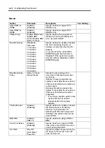
Page 88: ...C ESMPRO Agent Boot Monitoring Policy Retry 3 Times Always Reset Specify the processing at the occurrence of timeout during boot monitoring If Retry 3 times is selected the system is reset after the o...

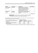
Page 89: ...ent filtering PEF feature Factory set IMPORTANT To power on the server from the UPS Uninterruptible Power Supply select Server AC LINK Power On The table below shows the operation when the AC power to...

Page 90: ...mber of the chassis View only Chassis Serial Number Displays the serial number of the chassis View only Onboard LAN1 MAC Address Displays the MAC address of the onboard LAN port 1 View only Onboard LA...

Page 91: ...ate used for the interface with the remote console connected Flow Control None XON XOFF CTS RTS CTS RTS CD Specify the flow control method Terminal Type PC ANSI VT100 VT UTF8 Specify the type of remot...

Page 92: ...HTTP Port Number 80 Specify the TCP port number which the management LAN uses for HTTP communication HTTPS Disabled Enabled Set to Enabled to use HTTPS communication for Web interface HTTPS Port Numbe...

Page 93: ...ackup copy of setting information of NEC DianaScope NOTE Executing Save Custom Defaults Load Custom Defaults of BIOS SETUP does not save the settings you have made in BMC LAN Configuration menu Event...

Page 94: ...on on the device in the relevant indication To boot the server from a desired device the device must be registered as a boot device Up to eight boot devices can be registered 2 Pressing X after select...

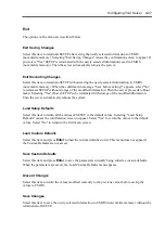
Page 95: ...be terminated with storage of the modified information Then the server automatically reboots the system Load Setup Defaults Select this item to return all the values of SETUP to the default values Sel...

Page 96: ...to be handled collectively In actual RAID can configure more than one HDDs as a single array disk group to operate the HDDs effectively This can bring higher performance than a single HDD of a large...

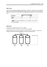
Page 97: ...table below Number of required HDDs RAID level Min Max RAID 0 1 3 RAID 1 2 2 NOTE For details of the RAID levels see RAID Levels described later in this chapter Disk Group A disk group is configured w...

Page 98: ...RAID Controller DG0 108 GB VD1 3 16 GB VD1 2 16 GB VD1 1 16 GB VD0 1 20GB VD0 2 20GB VD0 3 20GB VD0 RAID5 40 GB VD1 RAID5 32 GB Parity The parity means redundant data A single set of redundant data is...

Page 99: ...below lists the characteristics of the RAID levels Level Function Redundancy Characteristics RAID0 Striping No Data read write at the highest rate Largest capacity Capacity capacity of single HDD num...

Page 100: ...D is defected the data saved in the HDD cannot be recovered RAID Controller HDD 1 HDD 2 Stripe 1 HDD 3 Stripe 4 Stripe 2 Stripe 5 Stripe 3 Stripe 6 RAID1 In the RAID1 level data saved in a HDD is writ...

Page 101: ...umper switch on mother board NOTE The RAID System is factory set to Enabled WARNING Observe the following instructions to use the server safely Failure to follow these instructions may result in death...

Page 102: ...ther board 6 Change jumper setting as shown in the figure below J8 J7 J6 J5 J8 J7 J6 J5 1 2 3 1 2 3 Enable Disable 1 2 3 1 2 3 7 Reinstall the components removed in Step 2 8 Run the BIOS SETUP utility...

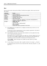
Page 103: ...n the following screen appears after you have powered on the server press Esc The POST screen appears 2 Check the description as shown below on the POST screen then press Ctrl M LSI Software RAID Conf...

Page 104: ...tware RAID Configuration Utility To quit the utility press Esc in the TOP menu of LSI Software RAID Configuration Utility When a confirmation message appears select Yes When the above message appears...

Page 105: ...ault Virtual Drive Virtual drive operation Virtual Drives Select virtual drive when multiple virtual drives exist Initialize Initialize virtual drive Check Consistency Check virtual drive redundancy V...

Page 106: ...Configuration Utility 1 Run LSI Software RAID Configuration Utility 2 Select Configure New Configuration from the TOP menu Management Menu Select View add Configuration to add configuration IMPORTANT...

Page 107: ...creen Upon completion of SCAN DEVICE the New Configuration ARRAY SELECTION MENU screen appears 4 Move the cursor onto the hard disk drive to be packed by using cursor key and then press Space to selec...

Page 108: ...electable RAID level varies depending on the number of hard disk drives that configure a pack 2 Size Sets virtual drive size Up to 8 virtual drives can be created per RAID Controller 3 DWC Sets parame...

Page 109: ...n select Yes to save the configuration 11 When the confirmation message shows that the configuration has been saved press Esc to return to the TOP menu screen 12 On the TOP menu screen select Objects...

Page 110: ...ncy on the virtual drive that has been initialized See Check Consistency for details 17 Press Esc to return to the TOP menu and exit from LSI Software RAID Configuration Utility IMPORTANT Be sure to e...

Page 111: ...he cursor onto the hard disk drive displaying FAIL and then press Space to select it Multiple hard disk drives can be selected simultaneous rebuilding The FAIL indication for the hard disk drive selec...

Page 112: ...as hot spare and then turn on the server 2 Run LSI Software RAID Configuration Utility 3 Select Objects Physical Drive from the TOP menu The Objects PHYSICAL DRIVE SELECTION MENU screen appears 4 Move...

Page 113: ...ID Configuration Utility IMPORTANT Select Objects Physical Drive Port X Force Offline to cancel the hot spare setting When two or more hard disk drives of the same capacity are assigned as hot spare r...

Page 114: ...onto the virtual drive to be checked and press Space to select it 4 When virtual drive has been selected press F10 to start consistency check 5 A confirmation screen for execution appears Select Yes...

Page 115: ...if you select the configuration information on the RAID Controller In this case execute Clear Configuration to create configuration again LSI Software RAID Configuration Utility cannot delete each vi...

Page 116: ...RAID Configuration Utility manages Adapter by a number beginning with 0 You can see a number of Adapter where Sel Adapter in Objects menu Universal RAID Utility manages RAID Controller by a number be...

Page 117: ...with 1 and ID The ID is same value of ID on LSI Software RAID Configuration Utility You can see a number and ID of Physical Device where Number and ID in the property of Physical Device on RAID Viewe...

Page 118: ...ate LSI Software RAID Configuration Utility Low 5 NOTES LSI Software RAID Configuration Utility can set FGI Rate Foreground Initialize and BGI Rate Background Initialize Priority But Universal RAID Ut...

Page 119: ...learing CMOS you must run the BIOS SETUP utility and execute the following menus to reconfigure your mother board Load Setup Defaults in the Exit menu Memory Retest of Memory Configuration in the Adva...

Page 120: ...self Make sure to complete board installation Do not install the server on a rack with leaving covers removed Do not pinch your finger with mechanical components Note high temperature Do not pull out...

Page 121: ...he top cover see Chapter 9 4 Verify the location of password clear jumper switch 5 Change jumper switch setting from Protect to Clear 6 Reassemble the server and press the POWER switch to turn on the...

Page 122: ...4 54 Configuring Your Server This page is intentionally left blank...
Page 123: ...andard Edition Microsoft Windows Server 2003 Enterprise Edition Microsoft Windows Server 2003 R2 Standard Edition Microsoft Windows Server 2003 R2 Enterprise Edition To use the server with the other o...

Page 124: ...p in order to save or backup parameters for installation If you want to set up the server as before execute the Express Setup with the parameter file you have saved before NOTES If you want to create...

Page 125: ...llation Confirm these notes before starting the Express Setup About the Windows family This computer supports the following Windows editions Microsoft Windows Server 2003 Standard Edition Microsoft Wi...

Page 126: ...erver 2003 R2 x64 Edition OS installation media with Service Pack 2 OS installation media No Service Pack Service Pack 2 OS installation media No Service Pack Windows Server 2003 R2 OS installation me...

Page 127: ...etup N8103 116 RAID controller 128 MB RAID0 1 N8103 117 RAID controller 128 MB RAID0 1 5 6 N8103 118 RAID controller 256 MB RAID0 1 5 6 Onboard RAID controller LSI Embedded MegaRAID Other controllers...

Page 128: ...llation About Removable Media Do not set removable media such as DAT into the device mounted on this computer during the Windows installation Connecting Hard Disk Drive Do not connect the other hard d...

Page 129: ...commended for collecting debug information memory dump The paging file with initial size large enough to store the dump file in the boot drive is required Correct debug information might not be able t...

Page 130: ...e size 2 See Chapter 5 and set that debugging information equivalent to the dump file size is to be written to a separate disk If the disk does not have enough free space to enable the dump file size...

Page 131: ...Save parameters Step 11 Next Start Express Setup Step 12 Next RAID Configuration Perform Create the OS partition format Copying Windows driver Copying Selected Application Remove the Floppy Disk and...

Page 132: ...ver 2 Insert the NEC EXPRESSBUILDER DVD into the optical disk drive of the server 3 Press the RESET switch or press Ctrl Alt and Delete to reboot from the NEC EXPRESSBUILDER You may also turn off and...

Page 133: ...not load parameters 1 Select Do not load parameters 2 Click Next NOTE If a floppy disk drive is not connected select this item Load parameters 1 Insert the floppy disk containing the parameters file 2...

Page 134: ...ayed Confirm the parameters modify if necessary and then click Next IMPORTANT Be sure to perform Consistency Check for the RAID drives configured by Express Setup NOTES You can use only the physical d...

Page 135: ...tion size larger than 2 097 152MB 2TB at RAID system If you select Create a new partition at Windows system drive settings the contents of the hard disk will be all deleted If Use existing partitions...

Page 136: ...s steps are displayed Confirm the parameters modify if necessary and then click Next NOTE Even if you do not input value into Administrator password Confirm password is displayed 10 Enter the setting...

Page 137: ...r workgroup name to be used Enter domain account steps are displayed Confirm the parameters modify if necessary and then click Next 12 Select the installing components Select Windows components steps...

Page 138: ...ed Confirm the parameters modify if necessary and then click Next 14 Save the parameters Save parameters steps are displayed If you want to save the parameters set the free formatted floppy disk Selec...

Page 139: ...ding to the message If you proceed the setup by using setup parameter file remove the floppy disk from the floppy disk drive Insert Windows Server 2003 CD ROM into the optical disk drive Agree Softwar...

Page 140: ...3 and selected applications will be installed automatically and rebooted several times After rebooting it logs on to the system automatically 20 If you install Microsoft Windows Server 2003 R2 insert...

Page 141: ...on test and so on Setup of teaming Configuring several network adapters as one team provides the server a tolerant environment on any trouble and enhances throughput between the switches PROSet is nec...

Page 142: ...e of the classic start menu Click Start menu point to Programs Accessories and click Windows Explorer 3 Run dxsetup exe in the following directory 007 win winnt dotnet dl3 proset win32 The Intel R PRO...

Page 143: ...ALB can be connected to only Switching Hub When exchange the mother board or option network card make sure to remove the adapter team before exchanges and recreate the adapter team after exchange comp...

Page 144: ...k Settings tab on TEAM xxx yy Properties 2 Click Modify Team 3 Point to the adapter Intel R PRO 1000 and click Set Primary or Set Secondary 4 Click OK 5 The setup will go back to EAM xxx yy Properties...

Page 145: ...not installed 1 The Local Area Connection Properties dialog box appears The procedure in the case of the standard start menu 1 Click Start menu Click Control Panel Click Network Connections and Click...

Page 146: ...click the Network Adapter Name in the Network Adapter list 2 Click the Link and specify the Speed and Duplex value the same as the value specified for HUB 3 Click Apply and click OK Also add or delete...

Page 147: ...ing N8104 123A Please refer to the installation manual provided with the board Installation of the Optional Network Board Driver 1 Start Device Manager 2 Click Network adapters and Double click Networ...

Page 148: ...nu is displayed close menu screen 2 Click Start menu point to Programs Accessories and click Windows Explorer 3 Run setup exe in the following directory 007 win winnt dotnet video setup exe 4 Follow t...

Page 149: ...e 4GB RAM tuning feature and the Physical Address Extension switch Below is the example on how to add PAE switch to Boot ini file 1 Click Start point to Settings and then click Control Panel 2 In Cont...

Page 150: ...ory Dump The staff of maintenance service representative is in charge of collecting memory dump Customers need only to specify the memory dump If any trouble occur after specifying the process below t...

Page 151: ...Verify the size of the empty space in the debugging information memory dump write destination drive Windows Server 2003 To specify Complete Memory Dump to write the debug information is recommended If...

Page 152: ...le size for all drives and click Set IMPORTANT The above mentioned paging file size is recommended for collecting debug information memory dump The paging file with initial size large enough to store...

Page 153: ...dows dialog box appears 3 Specify the location to store the diagnostic information in the Log File Path box The diagnostic information will be stored with the file name DRWTSN32 LOG NOTE You can not s...

Page 154: ...ve Windows Component The Windows Components Wizard dialog box appears 4 Click Management and Monitoring Tools and then click Details The Management and Monitoring Tools dialog appears 5 Click to selec...

Page 155: ...ocessor to multi processor Modified system configuration Recovered the system using recovery process See Updating the System Applying Service Pack section in Appendix D for detail of update process Ma...

Page 156: ...ice is RAID Controller configure the RAID system before running the NEC EXPRESSBUILDER 3 Boot the system from NEC EXPRESSBUILDER DVD 4 Select Load the optional driver into the EXPRESSBUILDER from the...

Page 157: ...Chapter 6 Installing and Using Utilities This section describes how to use the NEC EXPRESSBUILDER DVD that comes with your server and to install the utilities stored on the NEC EXPRESSBUILDER...

Page 158: ...ESSBUILDER referred to as EXPRESSBUILDER hereinafter helps you install the Operating system the Management software or use the maintenance utilities When you insert the EXPRESSBUILDER disk into the op...

Page 159: ...The configuration with Windows PE 2 0 supports Windows Server 2003 32bit and Windows Vista Business 32 bit x86 but the other operation is not supported You can use the Express Setup see Chapter 5 or t...

Page 160: ...used by the service representative See Chapter 8 BIOS FW Updating You can update the system BIOS by using the floppy disk prepare a 3 5 floppy disk ROM DOS Startup FD The ROM DOS Startup FD is used fo...

Page 161: ...If you want to operate this computer via the BIOS redirection the console less function select this item NOTE If you operate this computer via the Remote KVM function select the Tool menu Normal mode...

Page 162: ...ft Windows XP Vista or Windows Server 2003 or later Some documents are provided in PDF format Use the Adobe Reader to view or print these documents If the menu does not appear select My computer by us...

Page 163: ...lities automatically except for a few key input to confirm the specification Also you can install the system with the same specification as before when re installing the system We recommend you to cre...

Page 164: ...nstallation and creating Parameter file Follow the procedure below IMPORTANT Do not remove NEC EXPRESSBUILDER DVD from drive during a parameter file creation 1 Start the OS 2 Insert the NEC EXPRESSBUI...

Page 165: ...Installing and Using Utilities 6 9 4 Click Parameter File Creator Parameter File Creator will appear...

Page 166: ...nd Using Utilities 5 Load Parameters step is displayed Select Do not load parameters from the menu click Next 6 Select the installing Operating System Select Install the Windows 32bit editions from th...

Page 167: ...devices Parameter File Creator displays upper limit that the RAID controller can support The total of The number of physical devices used to create the logical drive and The number of the physical dev...

Page 168: ...larger than 2 097 152MB 2TB at RAID system If you select Create a new partition at Windows system drive settings the contents of the hard disk will be all deleted If Use existing partitions is selecte...

Page 169: ...ense mode Enter basic parameters steps are displayed Confirm the parameters modify if necessary and then click Next IMPORTANT Computer name and User name are required parameters NOTE Even if you do no...

Page 170: ...e displayed Confirm the parameters modify if necessary and then click Next NOTE The order of entry in custom setting may differ from the numbering of LAN port 11 Enter the domain or workgroup name to...

Page 171: ...components Select Windows components steps are displayed Confirm the parameters modify if necessary and then click Next 13 Select the installing applications Select applications steps are displayed Co...

Page 172: ...parameters steps are displayed If you want to save the parameters set the free formatted floppy disk Select Save parameters enter the file path of the parameters files into the text box and click Next...

Page 173: ...as been created Click Yes to exit Parameter File Creator NOTES If you modify existing information file parameter file click Load Parameters at Load Parameters screen Refer to help to modify informatio...

Page 174: ...Some features of NEC ESMPRO Manager include Hardware and software server configuration Hardware resources mounted in servers such as the CPU memory disks RAID System and LAN boards Software resources...

Page 175: ...Setup a dialog to specify an application appears Select Universal RAID Utility on the dialog Manual Setup Windows You can start the setup program of Universal RAID Utility from Autorun Menu Click Setu...

Page 176: ...ity doesn t have the function of management to computer installed RAID Controller via network If you want to manage it via network please use the function of remote console ex Remote Desktop of Window...

Page 177: ...e remote management of this server See the online documents for details on the functions and installation of NEC DianaScope NOTE You need the server license to activate DianaScope for this product The...

Page 178: ...6 22 Installing and Using Utilities This page is intentionally left blank...
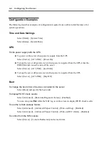
Page 179: ...dware configuration or BIOS configuration select System Information Management and then Save of the Off line Maintenance Utility to make a backup copy of the system information Also make a backup copy...

Page 180: ...e repair or alter the server Do not look into the optical disk drive Do not remove the lithium battery Disconnect the power plug before working with the server CAUTION Observe the following instructio...

Page 181: ...e server must be kept dry Do not moisten them with water 1 Make sure that the server is off powered the POWER LED goes off 2 Unplug the power cord of the server from a power outlet 3 Wipe off dust fro...

Page 182: ...ll vacuum cleaner with plastic tipped nozzle and electrostatic protection computer grade canned air and a small brush for cleaning the interior Follow the procedure below to clean the interior of the...

Page 183: ...4 Take out the ball from the mouse Cover the bottom of the mouse with your hand and turn your hand holding the mouse the mouse is on your palm with the button upward The mouse ball is released onto yo...

Page 184: ...the tray NOTE Do not touch the signal side of the disc with your hand 4 Wipe the tray with a dry soft cloth IMPORTANT Do not wipe the lens of the optical disk drive Doing so may damage the lens and ma...

Page 185: ...stem Test Items The following items are tested in system diagnostics Memory CPU cache memory Hard disk drive used as a system IMPORTANT When executing the system diagnostics make sure to disconnect th...

Page 186: ...to execute System Diagnostics with remote console The LAN connection is not for System Diagnostics Procedures to start the diagnostics program are as follows 1 Shutdown the OS and power off the server...

Page 187: ...stics tool title Shows the name and version of the diagnostic tool Test window title Shows the progress of the diagnostics Test End is displayed when the diagnostics completes Test result Shows the st...

Page 188: ...e log information of the diagnostics It can be saved on a floppy disk To save it on a floppy disk insert a formatted floppy disk to the floppy disk drive and select Save F Option Optional features can...

Page 189: ...eeds to be relocated stored due to a change in the floor layout to a great extent contact your service representative Make sure to make a backup copy of your valuable data in the hard disk drive if an...

Page 190: ...7 12 Maintenance This page is intentionally left blank...

Page 191: ...Troubleshooting If your server does not operate as expected read this chapter before assuming a failure NOTE For provision against an unexpected failure it is recommended to install NEC ESMPRO to your...

Page 192: ...NEC ESMPRO during the system operation Especially take note on whether any alert is reported to NEC ESMPRO Manager on the language PC Check whether any alert is reported on the Operation Window DataV...

Page 193: ...he front panel stays lit in green when the server is in successful operation When the STATUS LED is unlit blinking in green or lit blinking in amber it indicates that the server has failed The followi...

Page 194: ...ror occurred Cycle power to the server If POST displays an error message take a note on the message and contact your service representative Off Memory dumping is requested Wait until memory dumping co...

Page 195: ...lly equipped with the server If the power is supplied to the server and the hub and they are correctly connected with each other the LED is lit green LINK state If information is transmitted through a...

Page 196: ...blinking amber or green Indicates that the hard disk drive is being rebuilt this status is not a failure If the defected hard disk drive is replaced with a new one in the disk array configuration the...

Page 197: ...yboard instruction simultaneous key entry of Ctrl Alt Delete Immediately after the system is rebooted in response to an OS instruction During hardware initialization following restart of the POST When...

Page 198: ...ive 0230 System RAM Failed at offset 0231 Shadow Ram Failed at offset 0232 Extended RAM Failed at address line Contact your service representative 0250 System battery is dead Replace and run SETUP Con...

Page 199: ...ed 0B33 FAN4 Alarm occurred 0B34 FAN5 Alarm occurred 0B35 FAN6 Alarm occurred 0B36 FAN7 Alarm occurred 0B37 FAN8 Alarm occurred 0B38 FAN9 Alarm occurred 0B39 FAN10 Alarm occurred 0B3A FAN11 Alarm occu...

Page 200: ...0B91 BMC update firmware corrupted Turn off the power once and then on again to start the server If the error cannot be corrected contact your service representative 0B92 Internal Use Area of BMC FRU...

Page 201: ...03 Memory Error detected in DIMM group 4 8104 Memory Error detected in DIMM group 5 8105 Memory Error detected in DIMM group 6 Contact your service representative to replace the DIMM in the relevant g...

Page 202: ...epresentative to replace the failed DIMM or mother board 1 3 1 3 Keyboard controller error 1 Check if the keyboard is properly connected 2 Replace the mother board 1 3 3 1 No memory or capacity check...

Page 203: ...end from BIOS Message send from BMC Example Messages displayed on upper line BIOS message On screen message Description Action XX BIOS Rev YYYY POST in progress XX POST code YYYY BIOS version Wait unt...

Page 204: ...DUMP Request Dump switch is pressed Wait for completion of memory dump collection OS shutdown Alm OS stop error occurred Take note of on screen message wait for completion of memory dump collection th...

Page 205: ...server Make sure to use the power cord provided with the server Check the power cord for broken shield or bent plugs Make sure the power breaker for the connected power outlet is on If the power cord...

Page 206: ...nd power cord are properly connected Also make sure that the cables are connected in the correct order T Is the power on order correct When the server has any external devices connected power on the e...

Page 207: ...along with the OS Some OS s allow you to change the keyboard and mouse settings Refer to manual that comes with your OS to check that the keyboard and mouse settings are correct Fail to access to the...

Page 208: ...ternal SCSI devices connected hard disk drive settings including SCSI ID and terminator are required Refer to the manual that comes with the SCSI device for details T Are the SCSI controllers includin...

Page 209: ...onfiguration Onboard LAN LAN Controller T Have the protocol and service already configured Install the distinctive network driver for the server Make sure that the protocol such as TCP IP and services...

Page 210: ...PRO 1000 has been deactivated from the team Event Type Error Event Source IANSMiniport Event Category None Event ID 16 Description Team 0 The last adapter has lost link Team network connection has bee...

Page 211: ...D7 to the user NT AUTHORITY LOCAL SERVICE SID S 1 5 19 This security permission can be modified using the component Services administrative tool It is not a problem in operating the system There are s...

Page 212: ...ided by Windows Server 2003 R2 above shown event log will be registered For more details refer to Enabling Microsoft Windows Server 2003 R2 Hardware Management on the following site NEC Express5800 We...

Page 213: ...not turn the power OFF at the blue screen If you want to turn off the power at the blue screen execute forced shutdown forced shutdown continue to press POWER switch for 4 seconds The power will not b...

Page 214: ...On LAN feature does not work Immediately after the AC power is turned on the Remote Power ON OFF feature Wake ON LAN is disabled Start Windows 2003 once provide settings as shown below then shutdown t...

Page 215: ...is message appears check the error and take the appropriate corrective action according to the message listed in the table below Message Cause This EXPRESSBUILDER version was not designed for this com...

Page 216: ...hard disk drive and then retry the setup Specified to join the Domain but the system is installed as Workgroup When the setup fails to join the Domain during the installation it will install the syst...

Page 217: ...pear T Is your system Windows XP or later or Windows 2003 or later The Windows Autorun menu is supported by Windows XP Windows 2003 or later If your system runs on Windows Autorun Menu on Windows 2000...

Page 218: ...AID Controller may be failed Contact your service representative Rebuild fails T Is the capacity of the hard disk drive to be rebuilt sufficient The hard disk drive to be rebuilt should have the same...

Page 219: ...tact your service representative Physical device is not correctly displayed on Universal RAID Utility If you use LSI Embedded MegaRAID a part of information on a physical device is not correctly displ...

Page 220: ...ile the server is in the successful operation may affect the system operation Restarting the system due to an error may display a message indicating insufficient virtual memory Ignore this message and...

Page 221: ...the specified directory Memory dumping may not be available when the CPU stalls IMPORTANT Do not use a toothpick or plastic stick that is easy to break Recovery for Windows Server 2003 x64 Editions a...

Page 222: ...with your server into the optical disk drive of your server 3 Press Ctrl Alt and Delete to reboot the server from the NEC EXPRESSBUILDER You may also turn off and then on again to reboot the server Sy...

Page 223: ...nese starts by the automatic operation when the operation is not done for five seconds after the Language Selection menu is displayed 5 English is selected The tool menu is displayed When you use a lo...

Page 224: ...details of the Off line Maintenance Utility For further information ask your service representative The Off line Maintenance Utility provides the following features IPMI Information Viewer Provides t...

Page 225: ...turn off the server while the update program is running If the update processing is discontinued the system becomes unable to start ROM DOS startup FD Creates a support disk for starting the ROM DOS...

Page 226: ...the system administrator to set up the server from the management workstation management PC via the network or the server s COM B serial port IMPORTANT Do not use this feature on any other computer t...

Page 227: ...nfiguration file 3 5 inch floppy disk that includes communication method between the server and the management PC and various setup parameters Use NEC DianaScope or run System Management menu from NEC...

Page 228: ...ss FORCED SHUTDOWN Use this function when an OS command does not shut down the server the POWER switch does not turn off the server or resetting does not work Press and hold the POWER switch on the se...

Page 229: ...onal devices or the server or malfunctions of the server resulted from installation by the user NEC recommends you ask your service representative for install or removing any optional devices Make sur...

Page 230: ...the lithium battery Disconnect the power plug before working with the server CAUTION Observe the following instructions to use the server safely Failure to follow these instructions may cause a fire p...

Page 231: ...tic electricity Select a suitable work space Work with the server on the anti static or concrete floor When you work with the server on a carpet where static electricity is likely to be generated make...

Page 232: ...ocedure below to prepare for installing or removing components IMPORTANT Do not touch the riser card when holding the chassis after removing the top cover When removing the power cord from the server...

Page 233: ...rom the Rack Assembly in Chapter 3 Place the server on a rigid and flat desk IMPORTANT Be sure to remove the server from the rack Do not leave the server being pulled out from the rack 2 Remove the to...

Page 234: ...sure that the hooks on the top cover are inserted into the frame holes of the server certainly and put the top cover on the server Then move the top cover toward the front of the server Insert the end...

Page 235: ...ird party hard disk drive may cause a failure of the server as well as the hard disk drive All hard disk drives must accept the same interface Jumper switch setting on backplane board may need to be c...

Page 236: ...which you are going to install a hard disk drive The server has three slots Install hard disk drives starting from the leftmost slot 3 Remove the dummy tray Dummy trays are installed in all the hard d...

Page 237: ...OWER switch when installing or removing the hard disk drive Otherwise the system shutdown will occur 6 Close the handle gently The handle is locked when a distinct click is heard IMPORTANT Be careful...

Page 238: ...ritten on the hard disk drive Data not erased completely may be restored by special software and used for unexpected purposes It is strongly recommended that the software or service both available at...

Page 239: ...ss the POWER switch when installing or removing the hard disk drive Otherwise the system shutdown will occur 3 Firmly hold the handle and hard disk drive and pull out the hard disk drive 4 If using th...

Page 240: ...In addition do not put the DIMM on a desk directly See Static Precautions for details of the static electricity Do not use any DIMM not approved by NEC If an unapproved third party s DIMM is installed...

Page 241: ...ion If the DIMM is inserted into the DIMM socket the lever is automatically closed 1 Install the components removed in Step 1 2 Turn on the power of the server Make sure that no error message appears...

Page 242: ...ll the components removed in Steps 1 and 2 4 Turn on the power of the server Make sure that no error message appears in the POST If POST displays an error message take a note on the message and see th...

Page 243: ...tatic electricity Handle a board after making your body contact with a metallic frame section of the server to discharge the static electricity on your body Do not make bare hands contact with termina...

Page 244: ...N8103 117 RAID controller 128 MB RAID0 1 5 6 N8103 118 RAID controller 256 MB RAID0 1 5 6 N8104 111 100BASE TX adapter 32 bit 33MHz PCI N8104 112 1000BASE SX adapter 2ch 64 bit 133MHz PCI X Cannot coe...

Page 245: ...r card regardless of its shape IMPORTANT The server can contain a short type PCI board only not the long type one 1 See the section Preparing for Installation and Removal described earlier to prepare...

Page 246: ...your bare hand Fingerprints and dust left on them cause the server to malfunction due to a connection failure or damage to the leads If the board cannot be installed well remove the board once and th...

Page 247: ...h the riser card with your fingers until you cannot see any part of the riser card terminal section The riser card is now fully seated in the slot 7 Reassemble the server 8 Turn on the power of the se...

Page 248: ...r that is connected to the LAN port Disconnect the connector pushing the catch with a standard screwdriver At this time be very careful for the screwdriver not to damage the LAN port or other ports If...

Page 249: ...onfiguring the RAID System More than one hard disk drive is required to configure a Logical Drive Use hard disk drives of the same capacity and performance e g revolution for each pack to configure th...

Page 250: ...J8 J7 J6 J5 J8 J7 J6 J5 1 2 3 1 2 3 Enable Disable 1 2 3 1 2 3 Run the BIOS SETUP utility Select Advanced Peripheral Configuration SATA Controller Mode Option Enhanced Then select Advanced Peripheral...

Page 251: ...er terminals or on board parts by a bare hand or place the RAID Controller directly on the desk For static notes see the section Anti static Measures described earlier NOTE Before installing an option...

Page 252: ...Selection Others The installer automatically performs all the procedures for RAID System configuration and then maintenance utility installation When making the setup in manual mode use the RAID Syst...

Page 253: ...ay 3 slots PCI slot Standard configuration Low profile PCI EXPRESS x4 x 1 Full height PCI EXPRESS x8 x1 With optional riser card Low profile PCI EXPRESS x8 x1 Full height 32 bit 33MHz PCI x 1 Standard...

Page 254: ...A 2 Specifications This page is intentionally left blank...

Page 255: ...s with the server contains the NEC ESMPRO utility NEC recommends that you should install the NEC ESMPRO for effective use of the reliability enhancement features of the server Floppy Disk The followin...

Page 256: ...the floppy disk in a dusty place Do not place anything on the floppy disk Do not leave the floppy disk in a high temperature place e g place exposed to direct sunlight or close to a heater Do not lea...

Page 257: ...g system IMPORTANT Formatting a used floppy disk clears all the data contained in it if any Formatting a floppy disk from the DOS command line is not available with the server Use a formatted floppy d...

Page 258: ...its center to edge with a dry soft cloth slowly and gently Use the dedicated cleaner to clean the DVD CD ROM Do not use record spray cleaner benzene or thinner Keep the DVD CD ROM in the dedicated ca...

Page 259: ...ring alphanumeric characters or symbols IMPORTANT Do not pour any liquid such as water or put anything into the keyboard Doing so may cause a failure of the keyboard The keyboard provided with the ser...

Page 260: ...he mouse on a dusty or dirty desk disturbs smooth movement or normal operation of the mouse When your mouse movement seems dull clean your mouse See Chapter 7 Mouse operation includes Click Double cli...

Page 261: ...vice Interrupt Request The factory set IRQs are assigned as follows IRQ Peripheral Device Controller 0 System timer 1 2 3 COM2 serial port 4 COM1 serial port 5 6 7 PCI 8 Real time clock 9 ACPI Complia...

Page 262: ...C 2 IRQ This page is intentionally left blank...

Page 263: ...u want to install the other boards by using a driver floppy disk OEM FD for Mass storage device except ones listed below see Installing with the OEM FD for Mass storage device and Installing Optional...

Page 264: ...e it by yourself Updating System If you modified the Windows system execute Update the System in Autorun Menu Re installing to the Hard Disk Drive which has been upgraded to Dynamic Disk If you want t...

Page 265: ...insufficient so set an enough size of the paging file with the entire system Regardless of the size of the mounted memory or the Write debugging information type of memory dump the maximum size of th...

Page 266: ...or Installation NEC EXPRESSBUILDER DVD Microsoft Windows Server 2003 R2 Standard x64 Edition CD ROM Microsoft Windows Server 2003 R2 Enterprise x64 Edition CD ROM Windows Server 2003 x64 Editions Serv...

Page 267: ...SBUILDER use this procedure If Windows Server 2003 can be operated on NEC Express5800 Server you can use the other procedure described later Follow the steps below 1 Prepare one 3 5 inch floppy disk 2...

Page 268: ...elow 1 Prepare one 3 5 inch floppy disk 2 Start the Operating System 3 Insert the NEC EXPRESSBUILDER DVD into the optical disk drive of the server The Menu will appear 4 Click Create drive disk and se...

Page 269: ...inspecting your computer s hardware configuration is displayed A screen with a solid blue background is displayed IMPORTANT There is no visible indication on screen when F6 has been pressed 5 When the...

Page 270: ...up IMPORTANT If you install Windows Server 2003 x64 Editions on the hard disk larger than 2 097 152MB 2TB you can specify only a value equal to or less than 2 097 152MB as partition size 11 When the i...

Page 271: ...Be sure to make backup copies before re installing the operation system just in case Re installing the Operation System 1 Start the clean installation following the procedure described in this manual...

Page 272: ...Path 4 Click Yes 5 Choose the Assign a drive letter and specify the drive letter you want to assign 6 Click OK 7 If the following message appears click Yes Changing the drive letter of a volume may c...

Page 273: ...again when Windows Server 2003 x64 Editions CD ROM where ServicePack 2 is included is used and it is installed If you install Windows Server 2003 x64 Editions CD ROM which contains Service Pack 2 you...

Page 274: ...PRESSBUILDER DVD into the optical disk drive of the server 3 Click Start menu and Run and then execute the following command When Windows Server 2003 x64 Editions is used 007 win winnt w2k3amd qfe enu...

Page 275: ...s CD ROM that contains Service Pack 2 to your system you do not have to apply Service pack 2 again 1 Log on to the system with the account that has administrative privilege e g administrator 2 Insert...

Page 276: ...ystem the following message may be shown but there is no impact to the operation Do not click cancel since it may be taken away after a few seconds 4 Click OK to restart the system 5 When the reboot i...

Page 277: ...tab and then click OK Hide extensions for know file type Hide protected operating system files Recommended When the message You have chosen to display protected operating system files is displayed cl...

Page 278: ...ained in network driver Utilizing PROSet enables the following items Confirm detailed information of the adapter Diagnose loop back test packet transmission test and so on Setup of teaming Configuring...

Page 279: ...icense agreement and click Next 6 Click Next 7 Choose I accept the terms in the license agreement and click Next 8 Click Install 9 When InstallShield Wizard Completed window is displayed click Finishe...

Page 280: ...an be connected to only Switching Hub When exchange the mother board or option network card make sure to remove the adapter team before exchanges and recreate the adapter team after exchange complete...

Page 281: ...ttings tab on TEAM xxx yy Properties 2 Click Modify Team 3 Point to the adapter Intel R PRO 1000 and click Set Primary or Set Secondary 4 Click OK 5 The setup will go back to EAM xxx yy Properties and...

Page 282: ...installed 1 The Local Area Connection Properties dialog box appears The procedure in the case of the standard start menu 1 Click Start menu click Control Panel click Network Connections and click Loc...

Page 283: ...k Adapter list 2 Click the Link and specify the Speed and Duplex value the same as the value specified for HUB 3 Click Apply and click OK Also add or delete any protocols and services if necessary You...

Page 284: ...104 123A Please refer to the installation manual provided with the board Installation of the Optional Network Board Driver 1 Start Device Manager 2 Click Network adapters and double click Network Adap...

Page 285: ...ESSBUILDER DVD into the optical disk drive If the autorun menu is displayed close menu screen 2 Click Start menu point to Programs Accessories and click Windows Explorer 3 Run setup exe in the followi...

Page 286: ...hed to your system The SCSI controller driver will be installed automatically Installing SCSI Controller Driver N8103 95 The SCSI controller driver will be installed automatically Installing SAS Contr...

Page 287: ...ows Server 2003 x64 Editions must be activated before you can use Windows Server 2003 x64 Editions Windows activation process is as follows 1 Click Run on Start menu Type as follows in the Open box an...

Page 288: ...64 Editions The following screen is displayed 3 Process Windows activation according to the following message SETTING FOR COLLECTING MEMORY DUMP DEBUG INFORMATION Set for collecting memory dump using...

Page 289: ...nt to install the other boards by using a driver floppy disk OEM FD for Mass storage device except ones listed below see Installing with the OEM FD for Mass storage device and Installing Optional Mass...

Page 290: ...ice Pack You can install the Service Pack on the server When the Service Pack is not attached to your system prepare it by yourself When installing Windows Server 2003 R2 it is not necessary to apply...

Page 291: ...rver 2003 R2 The in place upgrade from Windows Server 2003 to Windows Server 2003 R2 is not recommended because it may overwrite any files or registries and cause unexpected impact to the system or th...

Page 292: ...so set an enough size of the paging file with the entire system The maximum paging file size which can be set on one partition is 4095MB If the above paging file size exceeds 4095MB specify 4095MB fo...

Page 293: ...dows Server 2003 Standard Edition CD ROM Microsoft Windows Server 2003 Enterprise Edition CD ROM Microsoft Windows Server 2003 R2 Standard Edition CD ROM Microsoft Windows Server 2003 R2 Enterprise Ed...

Page 294: ...ws Server 2003 or Windows can be operated on NEC Express5800 Server you can use the other procedure described later Follow the steps below 1 Prepare one 3 5 inch floppy disk 2 Turn on your NEC Express...

Page 295: ...low 1 Prepare one 3 5 inch floppy disk 2 Start the Operating System 3 Insert the NEC EXPRESSBUILDER DVD into the optical disk drive of the server The Menu will appear 4 Click Create drive disk and sel...

Page 296: ...when the window is in either of the following states Setup is inspecting your computer s hardware configuration or Press F6 if you need to install a third party SCSI or RAID driver is displayed A scr...

Page 297: ...sages that appear 9 If you utilize N8103 75 107 press S A list of mass storage devices is displayed Select the Adaptec Ultra320 SCSI Cards Windows 32 bit and press Enter 10 If you utilize N8103 95 pre...

Page 298: ...ter the application of System update Be sure to install Microsoft Windows Server 2003 R2 DISC 2 In this case note that the Windows Setup screen is not displayed 14 Insert Microsoft Windows Server 2003...

Page 299: ...which you want to install the operating system when the following message appears The following list shows the existing partitions and unpartitioned space on this computer Use the UP and DOWN ARROW ke...

Page 300: ...2 Specify the Disk Management in the left side of the window 3 Right click the volume you want to modify the drive letter and specify the Change Drive Letter and Path 4 Click Yes 5 Choose the Assign a...

Page 301: ...ion again following the procedure described in this manual 4 The drive letter of the re installed system may differ from the one of the previous system If you need to modify the drive letter modify it...

Page 302: ...figuration Recovered the system using recovery process The system update brings the correction program provided by Microsoft to be applied to reinforce the system security The system update is recomme...

Page 303: ...ive of the server 3 Click Start menu and Run and then execute the following command When the English version of Windows Server 2003 R2 is used 007 win winnt dotnet qfe enu kb921411 exe When the Simpli...

Page 304: ...E 16 Installing Windows Server 2003 5 When the following message is displayed make sure to click Finish to restart the system With that application process of the Hotfix KB921411 is finished...

Page 305: ...2 to your system you do not have to apply Service pack 2 again 1 Log on to the system with the account that has administrative privilege e g administrator 2 Insert the NEC EXPRESSBUILDER DVD into the...

Page 306: ...the following message may be shown but there is no impact to the operation Do not click cancel since it may be taken away after a few seconds 4 Click OK to restart the system 5 When the reboot is star...

Page 307: ...ab and then click OK Hide extensions for know file type Hide protected operating system files Recommended When the message You have chosen to display protected operating system files is displayed clic...

Page 308: ...ROSet is necessary to utilize these features Follow the procedure below to install PROSet 1 Insert the NEC EXPRESSBUILDER DVD into the optical disk drive If the autorun menu is displayed close menu sc...

Page 309: ...pop up menu 2 Click Configure The property dialog box for network adapter appears 3 Click the Advanced and specify the Link Speed Duplex value the same as the value specified for HUB 4 Click OK on the...

Page 310: ...erance AFT Adaptive Load Balancing ALB for reset the Adapter Fault Tolerance AFT Adaptive Load Balancing ALB Graphics Accelerator Driver If you utilize standard graphics accelerator drivers update you...

Page 311: ...Driver N8103 104 If you utilize SAS controller driver N8103 104 update your system with NEC EXPRESSBUILDER DVD attached to your system The SAS controller driver will be installed automatically About...

Page 312: ...E 24 Installing Windows Server 2003 2 When the screen as follows is displayed click Next The following screen is displayed 3 Process Windows activation according to the following message...

Page 313: ...tuning feature and the Physical Address Extension switch Below is the example on how to add PAE switch to Boot ini file 1 Click Start point to Settings and then click Control Panel 2 In Control Panel...

Page 314: ...E 26 Installing Windows Server 2003 SETTING FOR COLLECTING MEMORY DUMP DEBUG INFORMATION Set for collecting memory dump using the procedure described in Chapter 5...

Page 315: ...torun menu appears close the menu 3 Copy the below files of EXPRESSBUILDER to a hard disk by using Explorer root folder 007 copy version xml ar_menu copy this sub folder doc copy this sub folder win c...

Page 316: ...F 2 Using a Client Computer Which Has a CD Drive This page is intentionally left blank...

Page 317: ...lled Memory 1 Size Serial No Date Installed 2 Size Serial No Date Installed 3 Size Serial No Date Installed 4 Size Serial No Date Installed 5 Size Serial No Date Installed 6 Size Serial No Date Instal...

Page 318: ...rial No Date Installed Printer Model name Serial No Manufacturer Date Installed Additional Cabinet for Disk Model name Serial No Date Installed External Peripheral Device 1 Model name Serial No Manufa...

Page 319: ...le G 3 Software Firmware version OS Name Version Application of RUR media Apply Name Version File system FAT HPFS NTFS Others Bundled software installed Licensed software installed Application running...

Page 320: ...G 4 Product Configuration Record Table This page is intentionally left blank...
Reviews: