General Description 2-5
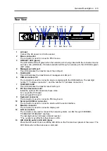
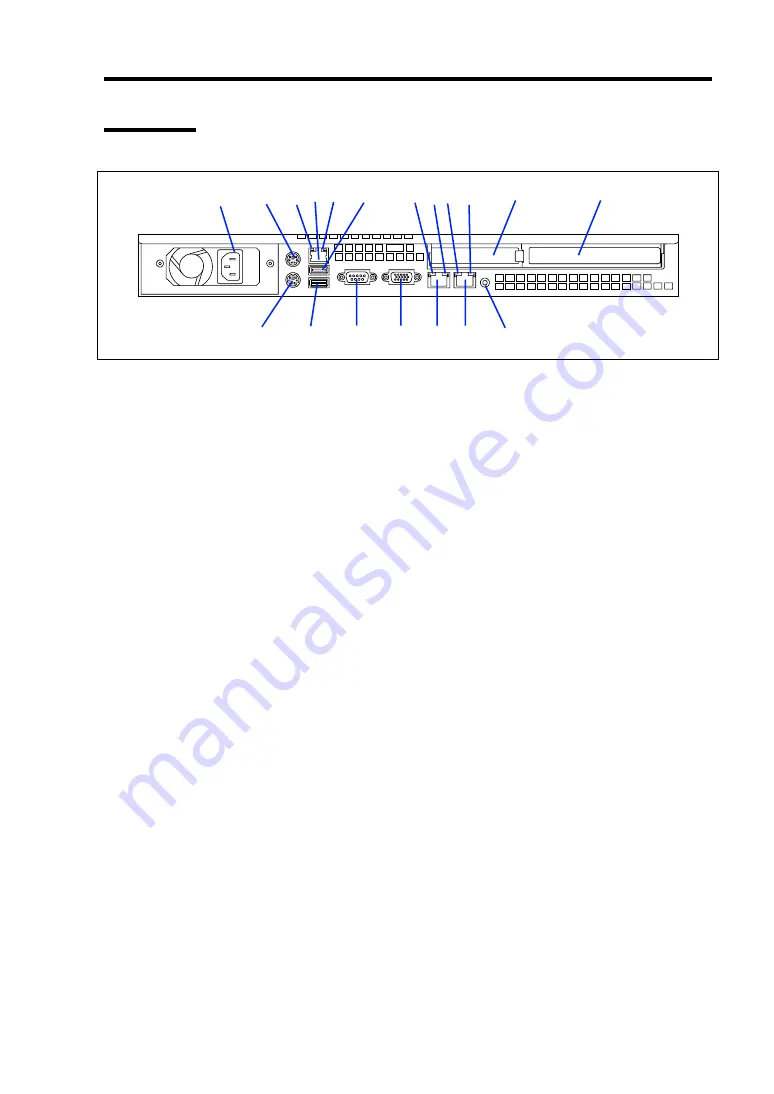
Rear View
1
AC inlet
Connect the AC power cord to this socket.
2
Mouse connector
The connector is used to connect a PS/2 mouse.
3
LINK/ACT LED (green)
The ACT/LINK LED is lit green when the network port is being linked with the connected device
such as a hub (LINK state). If a data is transferred through a network port, the LED blinks green
(ACT state).
4
Management LAN port
This LED indicates the transfer rate of the LAN port.
5
100/10 LED
This LED indicates the transfer rate of management LAN port.
6
USB connectors 1/2
The connector is used to connect a device compliant with the USB interface. The last digit
number "1" indicates connector 1, and the number "2" indicates connector 2.
7
1000/100/10 LED
This LED indicates the transfer rate of LAN port.
8
PCI board extension slot
Install the optional PCI board into these slots.
8-1 Low-profile PCI board
8-2 Full-height PCI board
9
Keyboard connector
The connector is used to connect a PS/2 keyboard.
10
Serial port (COM A) connector
The connector is used to connect a device with the serial interface.
11
Monitor connector
The connector is used to connect a display unit.
12
LAN connectors
The connectors are used to connect the network systems on LAN through 1000BASE-
T/100BASE-TX/10BASE-T interface.
The last digit number indicates LAN port number.
* The number may differ from that shown on OS.
13
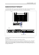
UID (Unit ID) switch / UID LED (blue)
Press the UID switch to turn on/off the UID LEDs on the front and rear panels of the server. The
LED blinks when software issues a command.
1
2
3
4 5
6
-1
7
8
-1
8
-2
9
10
6
-2
12
-1
12
-2
6
11
3
7
3
13
Summary of Contents for N8100-14522F
Page 16: ...x This page is intentionally left blank...
Page 122: ...4 54 Configuring Your Server This page is intentionally left blank...
Page 178: ...6 22 Installing and Using Utilities This page is intentionally left blank...
Page 190: ...7 12 Maintenance This page is intentionally left blank...
Page 254: ...A 2 Specifications This page is intentionally left blank...
Page 262: ...C 2 IRQ This page is intentionally left blank...
Page 316: ...F 2 Using a Client Computer Which Has a CD Drive This page is intentionally left blank...
Page 320: ...G 4 Product Configuration Record Table This page is intentionally left blank...

