2-4 General Description
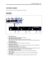
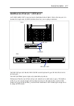
9 UID (Unit ID) switch
Press the UID switch to turn on/off the UID LED. Pressing the switch once turns on the LED.
Pressing it again turns it off.
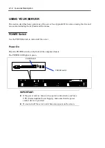
10 POWER switch
The POWER switch is used to turn the power of the server ON/OFF. If you press this switch
once, the power is turned on with the POWER LED going on green. If you press the switch
again, the power is turned off with the LED going off. Keep pressing the switch for 4 seconds
or more forcibly shuts down the system. This switch can be used as a SLEEP switch if the OS
supports sleep feature. In SLEEP Mode, this LED blinks.
11 NMI (DUMP) switch
Press this switch to dump system memory. In normal operation, this switch is not used.
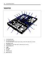
12 Hard disk drive bays
Up to three hard disk drives can be installed in the bays. The last-digit number indicates the
channel number. In the standard configuration, the dummy sponge blocks are installed in all
the bays.
13 DISK LED (green/amber)
LED on the hard disk drive. Each LED is green during access to the hard disk drive. The LED
turns amber when the hard disk drive fails. The LED blinks green and amber alternately
during rebuild processing (in disk array configuration).
Summary of Contents for N8100-14522F
Page 16: ...x This page is intentionally left blank...
Page 122: ...4 54 Configuring Your Server This page is intentionally left blank...
Page 178: ...6 22 Installing and Using Utilities This page is intentionally left blank...
Page 190: ...7 12 Maintenance This page is intentionally left blank...
Page 254: ...A 2 Specifications This page is intentionally left blank...
Page 262: ...C 2 IRQ This page is intentionally left blank...
Page 316: ...F 2 Using a Client Computer Which Has a CD Drive This page is intentionally left blank...
Page 320: ...G 4 Product Configuration Record Table This page is intentionally left blank...

