General Description 2-3
SYSTEM CHASSIS
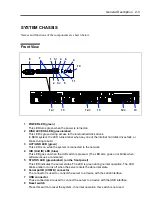
Names and functions of the components are shown below.
Front View
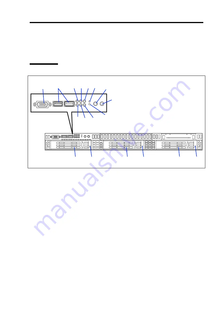
1 POWER LED (green)
This LED turns green when the power is turned on.
2 DISK ACCESS LED (green/amber)
This LED is green during access to the internal hard disk drives.
In RAID system, the LED turns amber when any one of the internal hard disk drives fails, or
blinks during rebuild.
3 ACT/LINK LED (green)
This LED is on while the system is connected to the network.
4 UID (Unit ID) LED (blue)
This LED goes on when the UID switch is pressed. (The LED also goes on or blinks when
software issues a command.)
5 STATUS LED (green/amber) (on the front panel)
This LED indicates the server status. The LED is green during normal operation. The LED
blinks amber or turns off when the server enters the abnormal state.
6 Serial port B (COM B) connector
The connector is used to connect the server to a device with the serial interface.
7 USB connector
These connectors are used to connect the server to a device with the USB interface.
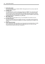
8 Reset switch
Press this switch to reset the system. In normal operation, this switch is not used.
6
7
1 3
-1
4
6
9
10
2 3
-2
5
11
12
-1
13
12
-2
13
12
-3
13
Summary of Contents for N8100-14522F
Page 16: ...x This page is intentionally left blank...
Page 122: ...4 54 Configuring Your Server This page is intentionally left blank...
Page 178: ...6 22 Installing and Using Utilities This page is intentionally left blank...
Page 190: ...7 12 Maintenance This page is intentionally left blank...
Page 254: ...A 2 Specifications This page is intentionally left blank...
Page 262: ...C 2 IRQ This page is intentionally left blank...
Page 316: ...F 2 Using a Client Computer Which Has a CD Drive This page is intentionally left blank...
Page 320: ...G 4 Product Configuration Record Table This page is intentionally left blank...

