


436
16. (G) Control Parameters
16.6 DC injection brake, zero speed control, servo lock, and magnetic flux decay output shutoff
NOTE
• When the setting of
Pr.12
is the initial value, the setting corresponding to the motor is set according to the
Pr.71 Applied motor
setting. (Refer to
.) However, when an energy saving motor (SF-HR or SF-HRCA) is used, change the
Pr.12
setting
as shown below.
• Even if the setting value of
Pr.12
is made larger, braking torque will be limited so the output current will be within the rated
current of the inverter.
Braking operation selection under Real sensorless vector control (Pr.850
= "0 or 1")
• The braking operation under Real sensorless vector control can be selected between the DC injection brake operation
(initial setting) and zero speed control.
By setting
Pr.850 Brake operation selection
= "1", zero speed control will be performed at the frequency set in
Pr.10 DC
injection brake operation frequency
or lower.
NOTE
• Under Real sensorless vector control, when the X13 signal turns ON while
Pr.11
= "8888", the zero speed control is activated
regardless of the
Pr.850
setting.
• When restarting the operation after a brake operation under Real sensorless vector control, set
Pr.850
= "1" (zero speed
control). Setting "0" (DC injection brake) may cause a delay of about 2 seconds from the time the start up command is input
until it actually is output.
Magnetic flux decay output shutoff and the Magnetic flux decay output
shutoff signal (X74 signal, Pr.850 = "2")
• Frequent starts/stops (inching) under Real sensorless vector control may cause an inverter failure or create a difference
in operation with the motor. The reason is that some magnetic flux is left in the motor at shutoff of the inverter output. If this
is the case, set
Pr.850
= "2" (magnetic flux decay output shutoff) or turn ON the Magnetic flux decay output shutoff (X74)
signal to decay the magnetic flux at a stop, and then shut off the output.
• While
Pr.850
= "2", deceleration starts at turning OFF of the start command, and the magnetic flux decay output shutoff is
activated when the estimated speed becomes lower than
Pr.10 DC injection brake operation frequency
.
• While the brake sequence function is active, the magnetic flux decay output shutoff is activated when the running frequency
drops to 0.5 Hz or
Pr.13 Starting frequency
, whichever is smaller.
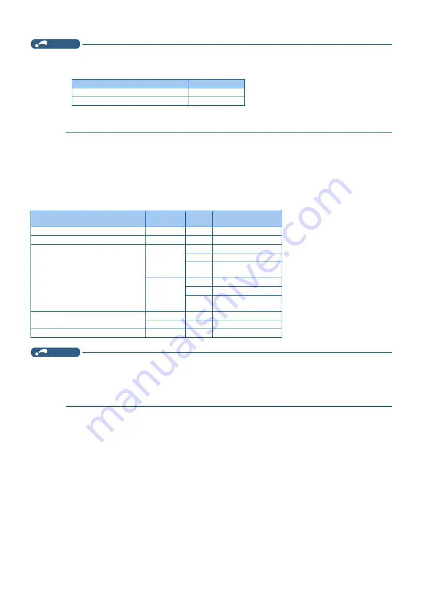
Motor capacity
Pr.12 setting
3.7 kW or lower
4%
5.5 kW or higher
3%
Control method
Control
mode
Pr.850
Deceleration stop
V/F control
—
—
DC injection brake
Advanced magnetic flux vector control
—
—
DC injection brake
Real sensorless vector control
Speed
0
DC injection braking
1
Zero speed
2
Magnetic flux decay
output shutoff
Torque
0
DC injection braking
1
Zero speed
2
Magnetic flux decay
output shutoff
Vector control
Speed
—
Zero speed or servo lock
Torque
—
Zero speed
PM sensorless vector control
Speed
—
DC injection brake
Summary of Contents for FR-E800
Page 17: ...16 1 Introduction 1 3 Related manuals MEMO ...
Page 51: ...50 2 Basic Operation 2 8 I O terminal function assignment MEMO ...
Page 89: ...88 3 Parameters 3 4 Parameter list by function group number MEMO ...
Page 135: ...134 5 Speed Control 5 9 Troubleshooting in the speed control MEMO ...
Page 153: ...152 6 Torque Control 6 7 Troubleshooting in torque control MEMO ...
Page 195: ...194 8 E Environment Setting Parameters 8 18 Current average value monitor signal MEMO ...
Page 237: ...236 10 D Operation Command and Frequency Command 10 6 Operation by multi speed setting MEMO ...
Page 339: ...338 13 T Multi Function Input Terminal Parameters 13 9 Start signal operation selection MEMO ...
Page 455: ...454 16 G Control Parameters 16 13 Speed smoothing control MEMO ...


