


240
11. (H) Protective Function Parameters
11.1 Motor overheat protection (electronic thermal O/L relay)
• When using the Mitsubishi Electric constant-torque motor, set the constant-torque motor in
Pr.71 Applied motor
referring
to
. (This setting enables the 100% constant-torque characteristic in the low-speed range.)
*1
When setting
Pr.9
to a value (current value) of 50% of the inverter rated current
*2
The % value denotes the percentage to the rated inverter current. It is not the percentage to the rated motor current.
*3
When the electronic thermal relay function dedicated to the Mitsubishi Electric constant-torque motor is set, this characteristic curve applies to
operation at 6 Hz or higher. (For selection of the operation characteristic, refer to
.)
*4
Transistor protection is activated depending on the temperature of the heat sink. The protection may be activated even with less than 150%
depending on the operating conditions.
NOTE
• The internal accumulated heat value of the electronic thermal relay function is reset to the initial value by the inverter's power
reset or reset signal input. Avoid unnecessary reset and power-OFF.
• Install an external thermal relay (OCR) between the inverter and motors to operate several motors, a multi-pole motor or a
dedicated motor with one inverter. When setting an external thermal relay, note that the current indicated on the motor rating
plate is affected by the line-to-line leakage current. The cooling effect of the motor drops during low-speed operation. Use a
motor with built-in thermal protector. (For details of the line-to-line leakage current, refer to the Instruction Manual
(Connection).)
• When the difference between the inverter and motor capacities is large and the set value is small, the protective characteristics
of the electronic thermal relay function will be deteriorated. Use an external thermal relay in such cases.
• A dedicated motor cannot be protected by an electronic thermal O/L relay. Use an external thermal relay.
• The transistor protection thermal O/L relay is activated early when the
Pr.72 PWM frequency selection
setting is increased.
Electronic thermal O/L relay when using PM motor (Pr.9)
• This function detects the overload (overheat) of the motor and shut off the inverter output by stopping the operation of the
transistor at the inverter output side.
• Set the rated current (A) of the motor in
Pr.9 Electronic thermal O/L relay
.
• Set "0" in
Pr.9
to avoid activating the electronic thermal relay function; for example, when using an external thermal relay
for the motor.
(Note that the output transistor protection of the inverter is activated. (E.THT))
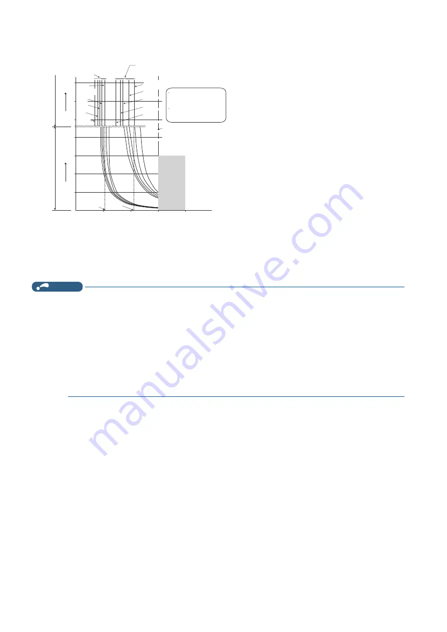
52.5%
105%
50
100
150
230
60
120
180
240
50
60
70
6Hz
20Hz
10Hz
6Hz
0.5Hz
30Hz or more*
3
20Hz
10Hz
0.5Hz
Pr. 9
= 50% setting
of inverter rating*
1.2
Pr. 9
= 100% setting
of inverter rating*
1.2
Second display in this region
Minute display in
this region
Operation time (min)
Operation time (s)
Characteristic when
electronic thermal relay
function for motor
protection is turned off
(When
Pr. 9
setting is 0(A))
30Hz
or more*
3
Inverter output power (%)
(% to the inverter rated current)
Operation region
Region on the right of
characteristic curve
Non-operation region
Region on the left of
characteristic curve
Range for
the transistor
protection
*4
Summary of Contents for FR-E800
Page 17: ...16 1 Introduction 1 3 Related manuals MEMO ...
Page 51: ...50 2 Basic Operation 2 8 I O terminal function assignment MEMO ...
Page 89: ...88 3 Parameters 3 4 Parameter list by function group number MEMO ...
Page 135: ...134 5 Speed Control 5 9 Troubleshooting in the speed control MEMO ...
Page 153: ...152 6 Torque Control 6 7 Troubleshooting in torque control MEMO ...
Page 195: ...194 8 E Environment Setting Parameters 8 18 Current average value monitor signal MEMO ...
Page 237: ...236 10 D Operation Command and Frequency Command 10 6 Operation by multi speed setting MEMO ...
Page 339: ...338 13 T Multi Function Input Terminal Parameters 13 9 Start signal operation selection MEMO ...
Page 455: ...454 16 G Control Parameters 16 13 Speed smoothing control MEMO ...


