11
12
13
14
15
16
17
18
19
20
435
16. (G) Control Parameters
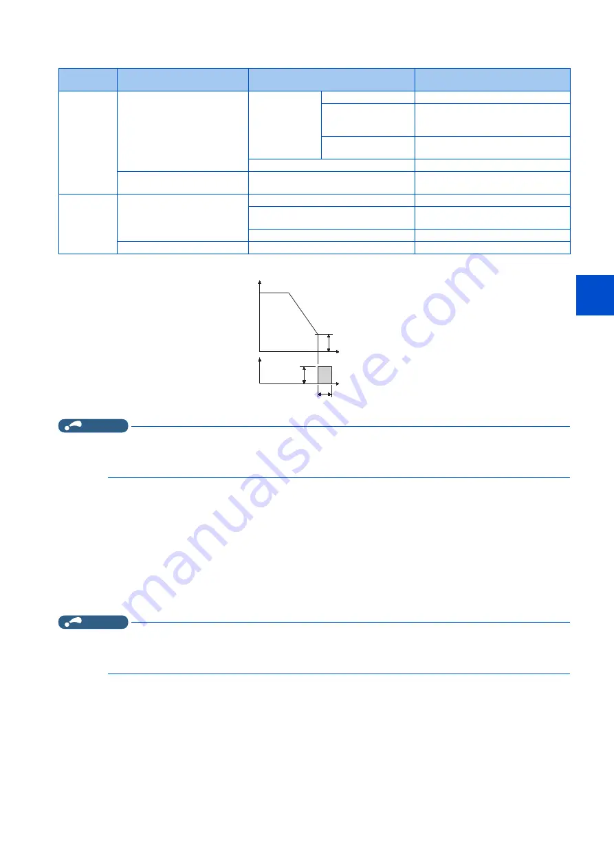
16.6 DC injection brake, zero speed control, servo lock, and magnetic flux decay output shutoff
• The DC injection brake operation frequency depends on the stopping method.
• The DC injection brake operation frequency will be fixed to 0 Hz under PM sensorless vector control.
NOTE
• When executing pre-excitation (zero speed control) under Real sensorless vector control, set
Pr.10 DC injection brake
operation frequency
to 0.5 Hz or lower since it may cause motor vibration, etc., at the time of deceleration stop.
• The initial value of
Pr.10
will automatically switch to 0.5 Hz under Vector control.
Operation time setting (X13 signal, Pr.11)
• Set the operation time for DC injection brake (zero speed control / servo lock) in
Pr.11 DC injection brake operation time
.
• When the motor does not stop due to large load moment (J), increase the setting to ensure the effect.
• When
Pr.11
= "0 s", DC injection brake (zero speed control / servo lock) does not start. (The motor starts to coast when
the output frequency drops to the
Pr.10
setting or lower at a stop.)
• When
Pr.11
= "8888", DC injection brake (zero speed control / servo lock) starts when the X13 signal is turned ON. DC
injection brake starts when the X13 signal is turned ON even while operating.
• For the X13 signal input, set "13" in any of
Pr.178 to Pr.189
to assign the function.
NOTE
• Under Real sensorless vector control, when the X13 signal turns ON while
Pr.11
= "8888", the zero speed control is activated
regardless of the
Pr.850 Brake operation selection
setting.
• Under Vector control, zero speed control or servo lock starts depending on the setting of
Pr.802
.
Setting of operation voltage (torque) (Pr.12)
• Set the percentage against the power supply voltage in
Pr.12 DC injection brake operation voltage
. (The setting is not
used for zero speed control or servo lock.)
• The DC injection brake operation is not available when the setting of
Pr.12
is 0%. (The motor starts to coast when the
output frequency drops to the
Pr.10
setting or lower at a stop.)
• The
Pr.12
setting is disabled under PM sensorless vector control.
Motor
Stopping method
Parameter setting
DC injection brake operation
frequency
Induction
motor
Press the STOP/RESET key on
the operation panel.
Turn OFF the STF/STR signal.
Pr.11
≠
"8888"
0.5 Hz or higher in
Pr.10 Pr.10
setting
Lower than 0.5 Hz in
Pr.10
, and 0.5 Hz or
higher in
Pr.13
0.5 Hz
Lower than 0.5 Hz in
both
Pr.10
and
Pr.13
Pr.10
or
Pr.13
setting, whichever larger
Pr.11
= "8888"
0.5 Hz
Set frequency to 0 Hz
—
Pr.13
setting or 0.5 Hz, whichever
smaller
PM motor
Press the STOP/RESET key on
the operation panel.
Turn OFF the STF/STR signal.
Pr.11
≠
"0, 8888"
0 Hz
Pr.11
= "0"
Motor coasts at the frequency set in
Pr.10
or lower.
Pr.11
= "8888"
0.5 Hz
Set frequency to 0 Hz
—
0 Hz
Time
Pr. 10 Operation
frequency
Time
Pr.12
Operation
voltage
voltage
Pr. 11 Operation time
Output
frequency
(Hz)
DC injection
brake
Summary of Contents for FR-E800
Page 17: ...16 1 Introduction 1 3 Related manuals MEMO ...
Page 51: ...50 2 Basic Operation 2 8 I O terminal function assignment MEMO ...
Page 89: ...88 3 Parameters 3 4 Parameter list by function group number MEMO ...
Page 135: ...134 5 Speed Control 5 9 Troubleshooting in the speed control MEMO ...
Page 153: ...152 6 Torque Control 6 7 Troubleshooting in torque control MEMO ...
Page 195: ...194 8 E Environment Setting Parameters 8 18 Current average value monitor signal MEMO ...
Page 237: ...236 10 D Operation Command and Frequency Command 10 6 Operation by multi speed setting MEMO ...
Page 339: ...338 13 T Multi Function Input Terminal Parameters 13 9 Start signal operation selection MEMO ...
Page 455: ...454 16 G Control Parameters 16 13 Speed smoothing control MEMO ...


