System Product Guide
5-17
Installing Video DRAM
▲
!
WARNINGS
Take care to correctly install the video DRAM chips. If installed
incorrectly, video DRAMs can overheat, resulting in damage to the
chips and possibly the system board.
If you think the video DRAMs might have been installed
incorrectly, shut down system power and allow a cooling period
before checking the chips for correct installation.
The optional video graphics controller comes with 1 MB of video DRAM
installed on the system board. You can also install an additional 1 MB of
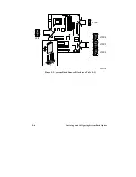
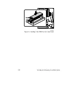
video DRAM. The additional memory plugs into the empty sockets shown
in Figure 5-6. Each socket holds a 256 KB x 16, 60 ns (or faster), SOJ DRAM
component. Both sockets must be empty or both must be populated. You do
not have to set any system jumpers if you install the additional video
memory.
Contact your service representative for a recommendation on specific part
numbers for installing the additional video DRAM.
Before you can install or remove video DRAM, you must remove the system
cover and any add-in boards that are blocking access to the video memory
sockets. After you are finished, replace any system parts you removed.
Refer to Chapter 4, "Taking Apart Your System," for the procedures to
remove and replace the system cover and add-in boards.
1. Remove one of the DRAMs from its antistatic package, being careful not
to touch the pins on the device.
2. Position the DRAM so its orientation mark (either a notch or a small dot
on the top of the short side) aligns with the end of socket that has a notch
(Figure 5-6). Align the pins on the DRAM with the socket.
3. Press the DRAM into the socket.
4. Repeat steps 1 through 3 to install the remaining DRAM in the
remaining empty video DRAM socket.
Summary of Contents for apricot VS660
Page 1: ...SYSTEM PRODUCT GUIDE VS660 apricot MITSUBISHI ELECTRIC ...
Page 2: ...Mini Tower System Product Guide ...
Page 51: ......
Page 55: ...4 4 Taking Your System Apart OM04061 A B A Figure 4 1 Removing the Side cover ...
Page 75: ......
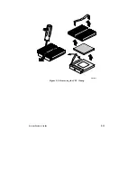
Page 86: ...System Product Guide 5 11 OM03834 Figure 5 3 Removing the CPU Clamp ...
Page 138: ......
Page 139: ......
Page 141: ......
Page 145: ......

