5-10
Installing and Configuring System Board Options
Installing the Upgrade
To install the upgrade, do the following:
1. Observe the precautions in “Before You Begin.” We recommend you
take the following steps to reduce the risk of electronic discharge
damage to the processor and system board components:
•
Touch the metal chassis before touching the processor or system
board. Keep part of your body in contact with the metal chassis to
dissipate the static charge while handling the processor.
•
Avoid moving around needlessly.
2. Turn off all peripheral devices connected to the system, and turn off the
system.
▲
!
WARNING
The microprocessor and heat sink may be hot if the system
has been running. To avoid the possibility of a burn, if
the system has been running let the processor and heat
sink cool for 10 minutes before going on with this
procedure.
3. Remove any add-in boards that block access to the socket.
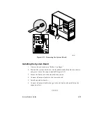
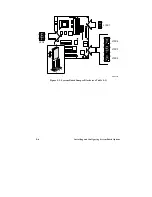
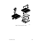
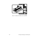
4. Figure 5-1 shows the location of the processor socket. You must first
remove the clamp over the heat sink and CPU. Insert a small flat-bladed
screwdriver into the slot on the end of the clamp. Release the clamp by
pushing outward on the blade of the screwdriver as shown in Figure 5-3.
As you move the clamp away from the socket, ease the clamp up and
away from the processor and heat sink. When you remove the clamp,
the heat sink will slide off the CPU.
▲
▲
!
CAUTION
When you remove the CPU clamp, avoid scraping the clamp
against any system board components.
Summary of Contents for apricot VS660
Page 1: ...SYSTEM PRODUCT GUIDE VS660 apricot MITSUBISHI ELECTRIC ...
Page 2: ...Mini Tower System Product Guide ...
Page 51: ......
Page 55: ...4 4 Taking Your System Apart OM04061 A B A Figure 4 1 Removing the Side cover ...
Page 75: ......
Page 86: ...System Product Guide 5 11 OM03834 Figure 5 3 Removing the CPU Clamp ...
Page 138: ......
Page 139: ......
Page 141: ......
Page 145: ......

