5-2
Installing and Configuring System Board Options
▲
!
WARNINGS
The procedures in this chapter assume familiarity with the general
terminology associated with personal computers and with the
safety practices and regulatory compliance required for using and
modifying electronic equipment.
The power supply in this system contains no user-serviceable
parts. To avoid personal injury or damage to your equipment,
refer repair or replacement of the power supply to qualified
personnel only. All other areas and components of this system are
considered user-accessible.
Disconnect the system from its power source and from any
telecommunications links, networks or modems before doing any
of the procedures described in this chapter. Failure to disconnect
power, telecommunications links, networks or internal modems
before you open the system or do any procedures can result in
personal injury or equipment damage.
Do not operate the system with the cover removed. Always
replace the cover before turning on the system.
▲
▲
!
CAUTIONS
The total power draw on the system must not exceed the
specifications for the power supply. See Chapter 7 for the power
supply specifications.
Electrostatic discharge (ESD) can damage disk drives, add-in boards,
and other components. Follow the procedures described in this
chapter only at an ESD workstation. If such a station is not
available, you can provide some ESD protection by wearing an
antistatic wrist strap and attaching it to a metal part of the system
chassis.
Add-in boards can be extremely sensitive to ESD and always require
careful handling. After removing the board from its protective
wrapper or from the system, place the board flat on a grounded,
static-free surface, component-side up. Use a conductive foam pad if
available, but not the board wrapper. Do not slide the board over
any surface.
Summary of Contents for apricot VS660
Page 1: ...SYSTEM PRODUCT GUIDE VS660 apricot MITSUBISHI ELECTRIC ...
Page 2: ...Mini Tower System Product Guide ...
Page 51: ......
Page 55: ...4 4 Taking Your System Apart OM04061 A B A Figure 4 1 Removing the Side cover ...
Page 75: ......
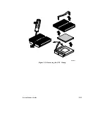
Page 86: ...System Product Guide 5 11 OM03834 Figure 5 3 Removing the CPU Clamp ...
Page 138: ......
Page 139: ......
Page 141: ......
Page 145: ......

