4-16
Taking Your System Apart
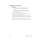
Installing a Drive in the 3.5-inch Drive Carrier
1. Observe the precautions in “Before You Begin.”
2. Remove the 3.5-inch drive carrier.
3. Remove the drive from its protective wrapper and place it on an
antistatic surface.
4. Set any jumpers, switches, or terminating resistors according to the
manufacturer’s instructions.
5. Slide the drive into the carrier until the screw holes line up.
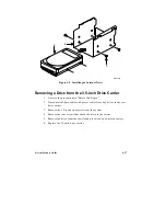
6. Secure the drive to the carrier with four screws (Figure 4-9, C) of the
appropriate size and length (not supplied).
7. Connect a power connector from the power supply to the drive. If the
drive is an IDE drive, connect the data cable between the drive and one
of the PCI/IDE connectors on the system board. If the drive is a non-
IDE type, refer to the drive manufacturer’s instructions for connecting a
data cable and interface board and for configuring the drive.
✏
Note
The system board provides two PCI/IDE headers for
connecting IDE hard drives. You can connect up to two IDE
drives (on the supplied cable) to each PCI/IDE header. If
one PCI/IDE header already has two drives connected to it,
you can connect additional IDE drives to the second
PCI/IDE header.
8. Replace the 3.5-inch drive carrier.
Summary of Contents for apricot VS660
Page 1: ...SYSTEM PRODUCT GUIDE VS660 apricot MITSUBISHI ELECTRIC ...
Page 2: ...Mini Tower System Product Guide ...
Page 51: ......
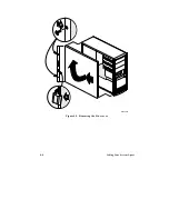
Page 55: ...4 4 Taking Your System Apart OM04061 A B A Figure 4 1 Removing the Side cover ...
Page 75: ......
Page 86: ...System Product Guide 5 11 OM03834 Figure 5 3 Removing the CPU Clamp ...
Page 138: ......
Page 139: ......
Page 141: ......
Page 145: ......

