System Product Guide
7-3
Board Connectors
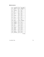
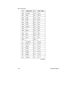
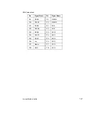
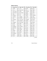
This section provides the pinouts for the system board connectors.
Chapter 5 shows the location of the connectors (Figure 5-1).
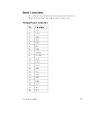
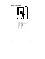
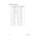
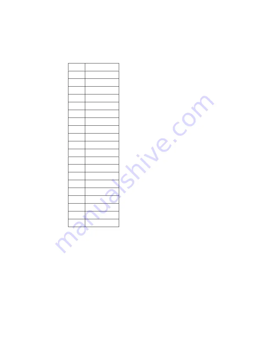
Primary Power Connector
Pin
Signal Name
1
3.3 V
2
3.3 V
3
GND
4
+5 V
5
GND
6
+5 V
7
GND
8
PWRGD
9
+5 V SB
10
+12 V
11
3.3 V
12
-12 V
13
GND
14
PS-
15
GND
16
GND
17
GND
18
-5 V
19
+5 V
20
+5 V
Summary of Contents for apricot VS660
Page 1: ...SYSTEM PRODUCT GUIDE VS660 apricot MITSUBISHI ELECTRIC ...
Page 2: ...Mini Tower System Product Guide ...
Page 51: ......
Page 55: ...4 4 Taking Your System Apart OM04061 A B A Figure 4 1 Removing the Side cover ...
Page 75: ......
Page 86: ...System Product Guide 5 11 OM03834 Figure 5 3 Removing the CPU Clamp ...
Page 138: ......
Page 139: ......
Page 141: ......
Page 145: ......

