4-22
Taking Your System Apart
Removing a 5.25-inch Device
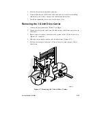
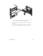
1. Observe the precautions in “Before You Begin.”
2. Disconnect the power and data cables attached to the device.
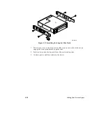
3. While squeezing the protruding plastic snap-in rails attached to the
device towards each other (Figure 4-12), carefully slide the device out of
the bay.
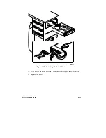
4. Replace the EMI shield and secure it to the chassis with a screw.
5. Replace the filler panel and secure it to the bezel with two screws.
Removing the System Board
1. Observe the precautions in “Before You Begin.”
2. Disconnect all internal cables connected to any add-in boards installed in
the expansion slots.
3. Remove all add-in boards.
4. Disconnect all internal cables connected to the system board.
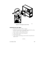
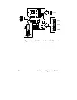
5. Remove the nine retaining screws and set them aside (Figure 4-13).
6. Carefully pop the board off of the snap-in standoff located near the card
retaining bracket (be careful not to flex the board) and lift the board out
of the chassis (Figure 4-13).
▲
▲
!
CAUTION
Be careful not to scrape any board components. Do not flex
the board. Place the board on a grounded, static-free surface
or in an antistatic protective wrapper.
Summary of Contents for apricot VS660
Page 1: ...SYSTEM PRODUCT GUIDE VS660 apricot MITSUBISHI ELECTRIC ...
Page 2: ...Mini Tower System Product Guide ...
Page 51: ......
Page 55: ...4 4 Taking Your System Apart OM04061 A B A Figure 4 1 Removing the Side cover ...
Page 75: ......
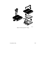
Page 86: ...System Product Guide 5 11 OM03834 Figure 5 3 Removing the CPU Clamp ...
Page 138: ......
Page 139: ......
Page 141: ......
Page 145: ......


