5-14
Installing and Configuring System Board Options
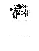
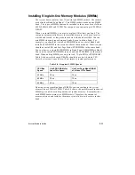
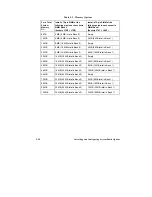
Table 5-5. Memory Options
For a Total
System
Memory
Of
…
…
Install a 72-pin SIMM of the
following size in each socket in
SIMM Bank 0
(Sockets
J7K3 + J7K2
)
Install a 72-pin SIMM of the
following size in each socket in
SIMM Bank 1
(Sockets
J7k1 + J6K1
)
8 MB
4 MB (8 MB total in Bank 0)
Empty
16 MB
4 MB (8 MB total in Bank 0)
4 MB (8 MB total in Bank 1)
16 MB
8 MB (16 MB total in Bank 0)
Empty
24 MB
8 MB (16 MB total in Bank 0)
4 MB (8 MB total in Bank 1)
32 MB
8 MB (16 MB total in Bank 0)
8 MB (16 MB total in Bank 1)
32 MB
16 MB (32 MB total in Bank 0)
Empty
40 MB
16 MB (32 MB total in Bank 0)
4 MB (8 MB total in Bank 1)
48 MB
16 MB (32 MB total in Bank 0)
8 MB (16 MB total in Bank 1)
64 MB
16 MB (32 MB total in Bank 0)
16 MB (32 MB total in Bank 1)
64 MB
32 MB (64 MB total in Bank 0)
Empty
72 MB
32 MB (64 MB total in Bank 0)
4 MB (8 MB total in Bank 1)
80 MB
32 MB (64 MB total in Bank 0)
8 MB (16 MB total in Bank 1)
96 MB
32 MB (64 MB total in Bank 0)
16 MB (32 MB total in Bank 1)
128 MB
32 MB (64 MB total in Bank 0)
32 MB (64 MB total in Bank 1)
Summary of Contents for apricot VS660
Page 1: ...SYSTEM PRODUCT GUIDE VS660 apricot MITSUBISHI ELECTRIC ...
Page 2: ...Mini Tower System Product Guide ...
Page 51: ......
Page 55: ...4 4 Taking Your System Apart OM04061 A B A Figure 4 1 Removing the Side cover ...
Page 75: ......
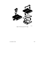
Page 86: ...System Product Guide 5 11 OM03834 Figure 5 3 Removing the CPU Clamp ...
Page 138: ......
Page 139: ......
Page 141: ......
Page 145: ......


