System Product Guide
3-13
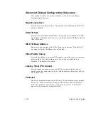
Serial Port 2 Address
Selects the address of the serial port. The options are Disabled; COM1, 3F8h,
IRQ4; COM2, 2F8h, IRQ3; COM3, 3E8h, IRQ4; and COM4, 2E8h, IRQ3. If the
Configuration Mode is set to Auto, the Setup program assigns the first free
COM port (normally COM2, 2F8h) as the serial port 2 address, regardless of
what is selected under the Serial Port 2 Address option. (If Configuration
Mode is set to Auto, this option cannot be modified.)
✏
Note
If either serial port address is set, the address it is set to will
not appear in the options dialog box of the other serial port.
If an ATI mach32
†
or an ATI mach64
†
video controller is
active, the COM4, 2E8h, IRQ3 address will not appear in the
options dialog box of either serial port.
Serial Port 2 IR Mode
Makes Serial Port 2 available to infrared applications. The options are
Enabled and Disabled. The default is Disabled. (If Configuration Mode is
set to Auto, this option cannot be modified.)
Parallel Port Address
Selects the address and IRQ of the parallel port. The options are Disabled;
LPT3, 3BCh, IRQ7; LPT1, 378h, IRQ7; LPT2, 278h, IRQ7; LPT3, 3BCh, IRQ5
LPT1, 378h, IRQ5; and LPT2, 278h, IRQ5. If the Configuration Mode is set to
Auto, the setup program assigns LPT1, 378h, IRQ7 as the parallel port
address, regardless of what is selected under the Parallel Port Address
option. (If Configuration Mode is set to Auto, this option cannot be
modified.)
Parallel Port Mode
Selects the mode for the parallel port. The options are Compatible, Bi-
directional, ECP, and EPP. The default is Compatible. Compatible means
the parallel port operates in AT-compatible mode. Bi-directional means the
parallel port operates in bi-directional PS/2-compatible mode. EPP and ECP
mean the parallel port operates high-speed, bi-directionally. This option is
not affected by the Configuration Mode field above.
Summary of Contents for apricot VS660
Page 1: ...SYSTEM PRODUCT GUIDE VS660 apricot MITSUBISHI ELECTRIC ...
Page 2: ...Mini Tower System Product Guide ...
Page 51: ......
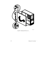
Page 55: ...4 4 Taking Your System Apart OM04061 A B A Figure 4 1 Removing the Side cover ...
Page 75: ......
Page 86: ...System Product Guide 5 11 OM03834 Figure 5 3 Removing the CPU Clamp ...
Page 138: ......
Page 139: ......
Page 141: ......
Page 145: ......

