System Product Guide
3-17
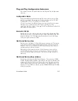
Plug and Play Configuration Subscreen
This section describes the options found on the Plug and Play configuration
subscreen.
Configuration Mode
Sets how the BIOS gets information about ISA cards that do not have Plug
and Play capabilities. The options are Use Setup Utility and Use ICU (ISA
Configuration Utility). The default is Use Setup Utility.
If Use ICU is selected, the BIOS will depend on run-time software to ensure
that there are no conflicts between ISA boards with Plug and Play
capabilities and those without. Choosing Use ICU enables Boot with PnP OS
and disables all other options.
Boot with PnP OS
Enables the PC to boot with an operating system capable of managing Plug
and Play add-in cards. The options are None, Other, and Windows 95. The
default is Windows 95. If Configuration Mode (above) is set to Use Setup
Utility, this option will not be visible.
ISA Shared Memory Size
Enables you to “unshadow” a block of the upper memory area. The options
are Disabled, 16 KB, 32 KB, 48 KB, 64 KB, 80 KB, and 96 KB. The default is
Disabled. If this is set to Disabled, the ISA Shared Memory Base Address
(described below) will not be visible.
Shadowing is a technique that copies a block of memory from an add-in
card’s ROM to the same address in system memory. This provides faster
access and achieves higher performance. By default, all upper memory is
shadowed.
ISA Shared Memory Base Address
Sets the base address for the ISA Shared Memory. The options are C8000h,
CC000h, D0000h, D4000h, D8000h, and DC000h. The default is C8000h. This
setting could affect the ISA Shared Memory Size item. The value entered in
the ISA Shared Memory Size item cannot extend to the E0000h address. For
example, if a size of 64K was selected, options D4000h, D8000h, and DC000h
will not be available.
Summary of Contents for apricot VS660
Page 1: ...SYSTEM PRODUCT GUIDE VS660 apricot MITSUBISHI ELECTRIC ...
Page 2: ...Mini Tower System Product Guide ...
Page 51: ......
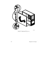
Page 55: ...4 4 Taking Your System Apart OM04061 A B A Figure 4 1 Removing the Side cover ...
Page 75: ......
Page 86: ...System Product Guide 5 11 OM03834 Figure 5 3 Removing the CPU Clamp ...
Page 138: ......
Page 139: ......
Page 141: ......
Page 145: ......

